82 YASKAWA ELECTRIC SIEP C710616 30B YASKAWA AC Drive T1000A Technical Manual
4.4 Start-Up Flowcharts
4.4 Start-Up Flowcharts
The flowcharts in this section summarize basic steps required to start the drive. Use the flowcharts to determine the most
appropriate start-up method for a given application. The charts are intended as a quick reference to help familiarize the
user with start-up procedures.
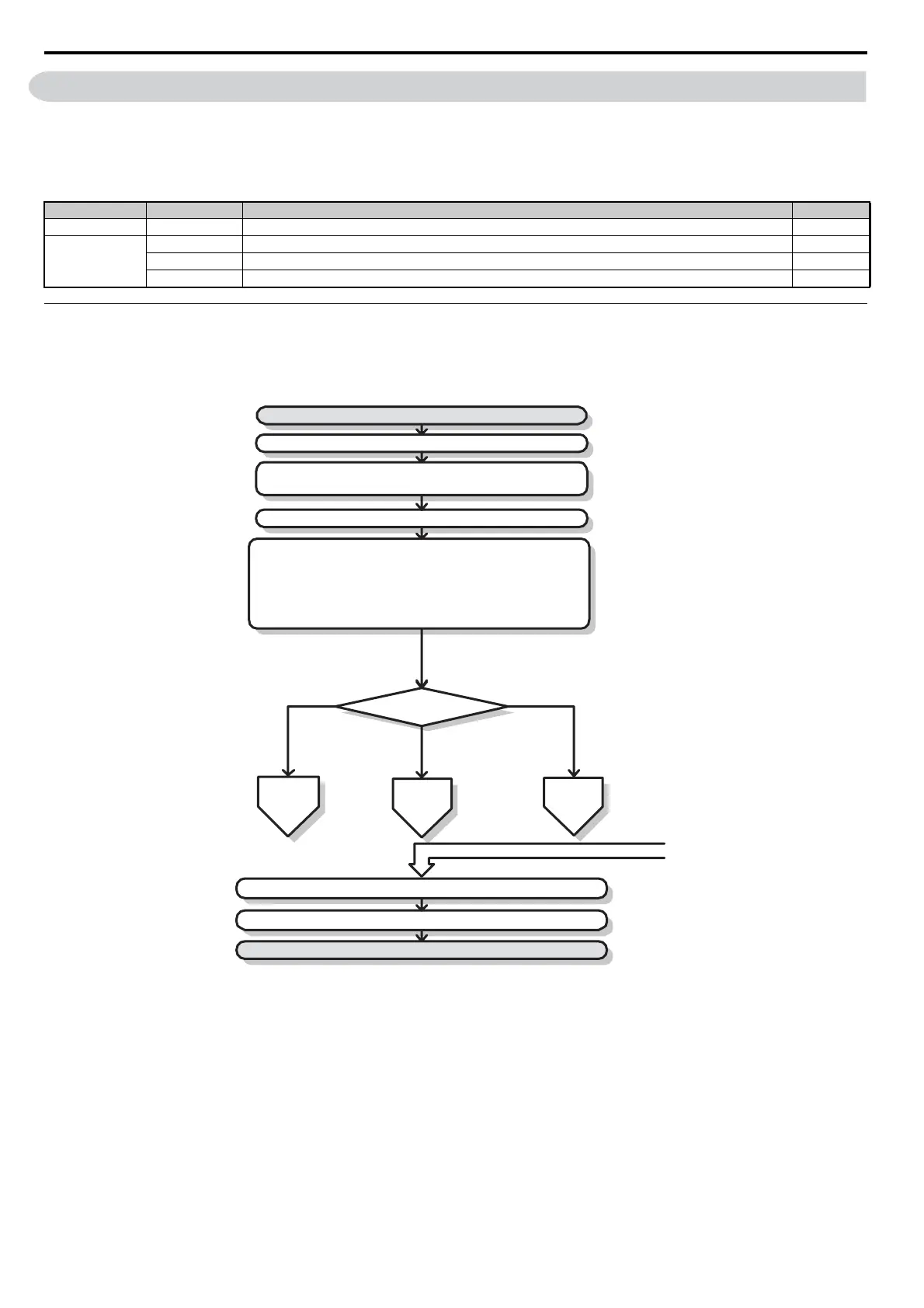
u Flowchart A: Basic Start-up and Motor Tuning
Flowchart A in Figure 4.7 describes a basic start-up sequence. Use drive default parameter settings in simple
applications that do not require high precision.
Figure 4.7
Figure 4.7 Basic Start-up
Note: 1. When the motor cable length has changed for more than 50 m after Auto-Tuning has been performed (e.g., after the drive has been set
up and then later installed in a different location), execute Stationary Auto-Tuning for resistance between motor lines once the drive
is installed in its final installation location.
2. Auto-Tuning should be performed again after installing an AC reactor or other such components to the output side of the drive.
Flowchart Subchart Objective Page
A – Basic startup procedure and motor tuning 82
–
A-1 Simple motor setup using V/f mode 83
A-2 High-performance operation using Open Loop Vector (OLV) or Closed Loop Vector (CLV) motor control 84
A-3 Setting up the drive to run a permanent magnet (PM) motor 85
START
Install and wire the drive as explained in Chapters 1, 2, and 3
Apply main power on to the drive
Adhere to safety messages concerning application of power
Set the control mode in parameter A1-02.
To
Flowchart A-1
Control Mode
A1-02 =
To
Flowchart A-2
To
Flowchart A-3
Set the basic parameters
b1-01/02 for frequency reference and run command source selection
H1-,H2-,H3-,H4-,H6-for I/O terminal setting
d1-for multi-speed references if used
C1- and C2-for accel./decel. and S-curve time settings
C6-01 for heavy/normal duty mode selection
L8-55 = 0 if a regen converter is used.
L3-04 if braking options are used
Fine tune parameters. Adjust application settings (PID, ...) if necessary.
Check the machine operation and verify parameter settings.
Drive is ready to run the application.
From Flowchart A-1, A-2, or A-3
0: V/f
1: V/f w/PG
2: OLV
3: CLV
5: OLV/PM
6: AOLV/PM
7: CLV/PM

 Loading...


