60 YASKAWA ELECTRIC SIEP C710616 30B YASKAWA AC Drive T1000A Technical Manual
3.8 Control Circuit Wiring
3.8 Control Circuit Wiring
u Control Circuit Connection Diagram
Refer to Standard Connection Diagram on page 46 when wiring terminals on the drive’s control circuit.
Figure 3.21
u Control Circuit Terminal Block Functions
Drive parameters determine which functions apply to the multi-function digital inputs (S1 to S8), multi-function digital
outputs (M1 to M6), multi-function analog inputs (A1 to A3), and multi-function analog monitor output (FM, AM). The
default setting is listed next to each terminal in Figure 3.1 on page 46.
WARNING! Sudden Movement Hazard. Always check the operation and wiring of control circuits after being wired. Operating a drive
with untested control circuits could result in death or serious injury.
n Input Terminals
Table 3.6 lists the input terminals on the drive. Text in parenthesis indicates the default setting for each multi-function
input.
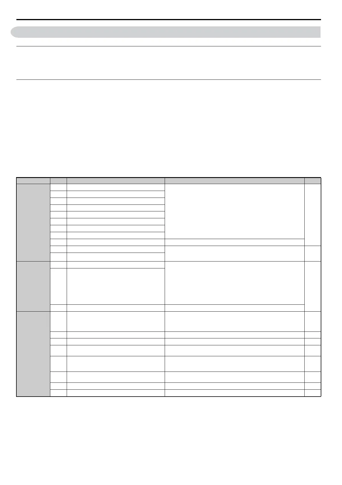
Table 3.6 Control Circuit Input Terminals
Type No. Terminal Name (Function) Function (Signal Level) Default Setting Page
Multi-Function
Digital Inputs
S1
Multi-function input 1 (Closed: Forward run, Open: Stop)
Photocoupler
24 Vdc, 8 mA
Set the wire jumper between SC and SN or SC and SP to select sinking/sourcing
mode and power supply.
Refer to Sinking/Sourcing Mode Switch for Digital Inputs on page 65.
181
S2
Multi-function input 2 (Closed: Reverse run, Open: Stop)
S3
Multi-function input 3 (External fault, N.O.)
S4
Multi-function input 4 (Fault reset)
S5
Multi-function input 5 (Multi-step speed reference 1)
S6
Multi-function input 6 (Multi-step speed reference 2)
S7
Multi-function input 7 (Jog reference)
S8
Multi-function input 8 (Baseblock)
SC
Multi-function input common Multi-function input common
SP
Digital input power supply +24 Vdc
24 Vdc power supply for digital inputs, 150 mA max (if no digital input option DI-
A3 is used only)
Never short terminals SP and SN as doing so will damage the drive.
65
SN
Digital input power supply 0 V
Safe Disable
Inputs
H1
Safe Disable input 1
24 Vdc, 8 mA
One or both open: Output disabled
Both closed: Normal operation
Internal impedance: 3.3 kΩ
Off time of at least 1 ms
Disconnect the wire jumpers shorting terminals H1, H2, and HC to use the Safe
Disable inputs. Set the jumper S3 to select between sinking, sourcing mode, and the
power supply as explained in Sinking/Sourcing Mode Selection for Safe Disable
Inputs on page 65.
490
H2
Safe Disable input 2
HC
Safe Disable function common Safe disable function common
Analog Inputs /
Pulse Train Input
RP
Multi-function pulse train input (Frequency reference)
Input frequency range: 0 to 32 kHz
Signal Duty Cycle: 30 to 70%
High level: 3.5 to 13.2 Vdc, low level: 0.0 to 0.8 Vdc
Input impedance: 3 kΩ
112
208
+V
Power supply for analog inputs 10.5 Vdc (max allowable current 20 mA) 111
-V
Power supply for analog inputs -10.5 Vdc (max allowable current 20 mA) –
A1
Multi-function analog input 1 (Frequency reference bias) -10 to 10 Vdc, 0 to 10 Vdc (input impedance: 20 kΩ)
111
201
A2
Multi-function analog input 2 (Frequency reference bias)
-10 to 10 Vdc, 0 to 10 Vdc (input impedance: 20 kΩ)
4 to 20 mA, 0 to 20 mA (input impedance: 250 Ω)
Voltage or current input must be selected by DIP switch S1 and H3-09
111
111
202
A3
Multi-function analog input 3 (Auxiliary frequency
reference) / PTC Input
-10 to 10 Vdc, 0 to 10 Vdc (input impedance: 20 kΩ)
Use DIP switch S4 on the terminal board to selection between analog or PTC input.
111
AC
Frequency reference common 0 V 111
E (G)
Ground for shielded lines and option cards – –