4.6 Auto-Tuning
YASKAWA ELECTRIC SIEP C710616 30B YASKAWA AC Drive T1000A Technical Manual 89
Start-Up Programming
& Operation
4
Table 4.10 Auto-Tuning Input Data
u Before Auto-Tuning the Drive
Check the items below before Auto-Tuning the drive.
n
Basic Auto-Tuning Preparations
• Auto-Tuning requires the user to input data from the motor nameplate or motor test report. Make sure this data is
available before Auto-Tuning the drive.
• For best performance, the drive input supply voltage must be at least equal to or greater than the motor rated voltage.
Note: Better performance is possible when using a motor with a base voltage that is 20 V (40 V for 400 V class models) lower than the
input supply voltage. This is particularly important when operating the motor above 90% of base speed, where high torque
precision is required.
• To cancel Auto-Tuning, press the STOP key on the digital operator.
• When using a motor contactor, make sure it is closed throughout the Auto-Tuning process.
• When using Auto-Tuning for motor 2, make sure motor 2 is connected to the drive output when performing the tuning.
• Table 4.11 describes digital input and output terminal operation while Auto-Tuning is executed.
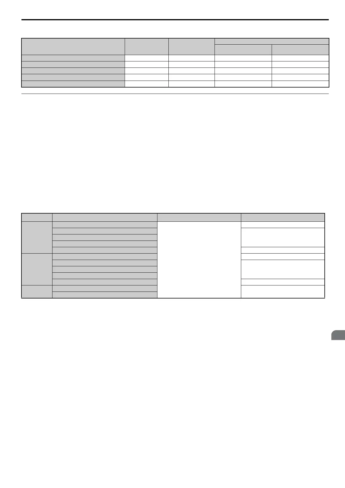
Table 4.11 Digital Input and Output Operation During Auto-Tuning
n Notes on Rotational Auto-Tuning
• To achieve optimal performance from Rotational Auto-Tuning, the load should be decoupled from the motor.
Rotational Auto-Tuning is best suited for applications requiring high performance over a wide speed range.
• If motor and load can not be decoupled, reduce the load so that it is no greater than 30% of the rated load. Performing
Rotational Auto-Tuning with a higher load will set motor parameters incorrectly, and can cause irregular motor
rotation.
• Ensure the motor-mounted brake is fully released if installed.
• Connected machinery should be allowed to rotate the motor.
n
Notes on Stationary Auto-Tuning
Stationary Auto-Tuning modes analyze motor characteristics by injecting current into the motor for about one minute.
WARNING! Electrical Shock Hazard. When executing stationary Auto-Tuning, the motor does not rotate, however, power is applied.
Do not touch the motor until Auto-Tuning is completed. Failure to comply may result in injury from electrical shock.
WARNING! Sudden Movement Hazard. If installed, do not release the mechanical brake during stationary Auto-Tuning. Inadvertent
brake release may cause damage to equipment or injury to personnel. Ensure that the mechanical brake release circuit is not
controlled by the drive multi-function digital outputs.
Stationary Auto-Tuning 1 and 2
• Perform these tuning methods when using a vector control mode but Rotational Auto-Tuning cannot be performed.
Input Value Input Parameter Unit
Tuning Type (T1-01 or T2-01)
8
Inertia Tuning
9
ASR Gain Tuning
Control Mode A1-02 - 3, 7 3, 7
Test signal frequency T3-01 Hz YES YES
Test signal Amplitude T3-02 rad YES YES
Motor inertia T3-03
kgm
2
YES YES
System response frequency T3-04 Hz N/A YES
Motor Type Auto-Tuning Type Digital Input Digital Output
IM Motor
Rotational Auto-Tuning
Digital input functions are disabled.
Functions the same as during normal operation
Stationary Auto-Tuning 1
Maintains the status at the start of Auto-Tuning
Stationary Auto-Tuning 2
Stationary Auto-Tuning for Line-to-Line Resistance
Rotational Auto-Tuning for V/f Control Functions the same as during normal operation
PM Motor
PM Motor Parameter Settings Digital output functions are disabled.
PM Stationary Auto-Tuning
Maintains the status at the start of Auto-Tuning
PM Stationary Auto-Tuning for Stator Resistance
Z Pulse Offset Tuning
Back EMF Constant Tuning Functions the same as during normal operation
IM and PM
Motors
Inertia Tuning
Functions the same as during normal operation
ASR Gain Auto-Tuning
 Loading...


