C.9 MEMOBUS/Modbus Data Table
YASKAWA ELECTRIC SIEP C710616 30B YASKAWA AC Drive T1000A Technical Manual 459
MEMOBUS/Modbus
Communications
C
C.9 MEMOBUS/Modbus Data Table
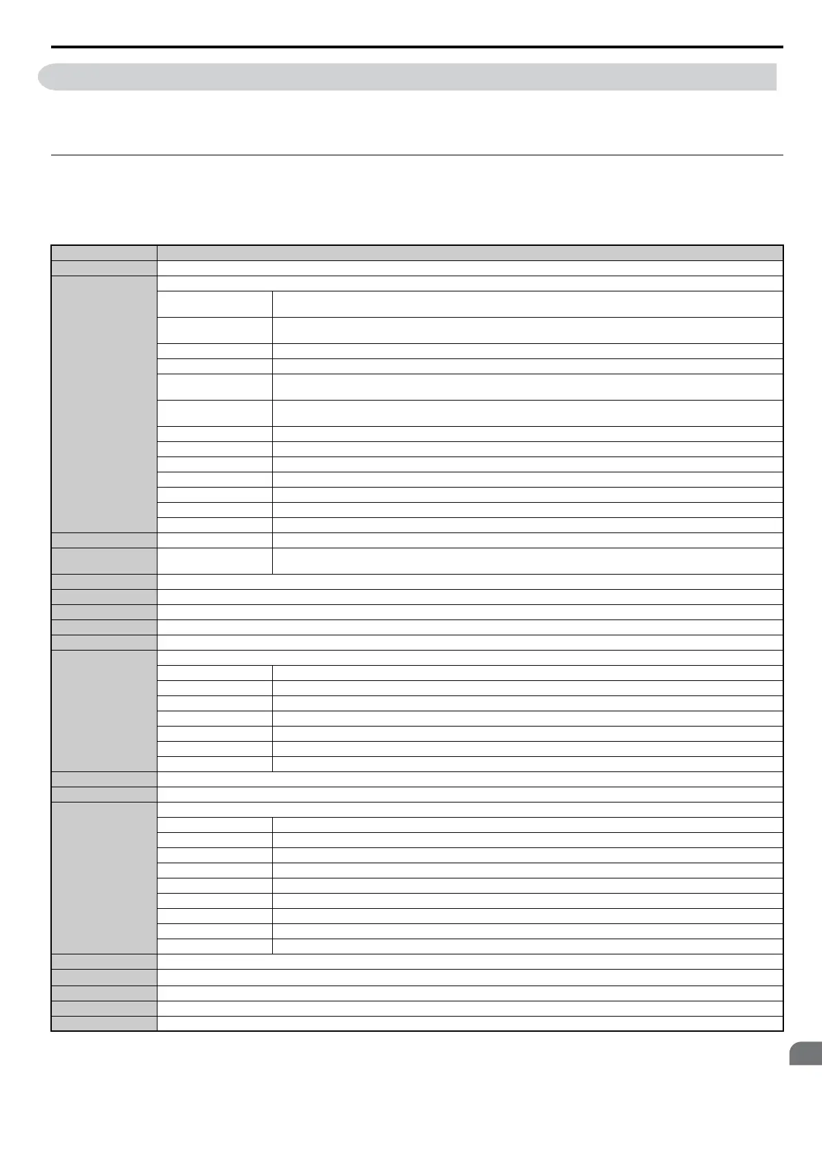
Table below lists all MEMOBUS/Modbus data. There are three types of data: command data, monitor data, and
broadcast data.
u Command Data
It is possible to both read and write command data.
Note: Bits that are not used should be set to 0. Refrain from writing to reserved registers.
Register No. Contents
0000H Reserved
0001H
Operation Commands and Multi-function Inputs
bit 0
H5-12 = 0: Forward Run Command (0 = Stop, 1 = Forward Run)
H5-12 = 1: Run Command (0 = Stop, 1 = Run)
bit 1
H5-12 = 0: Reverse Run Command (0 = Stop, 1 = Reverse Run)
H5-12 = 1: Forward/Reverse (0 = Forward, 1 = Reverse)
bit 2 External Fault (EF0)
bit 3 Fault Reset
bit 4
Multi-Function Input 1
Function is ComRef when H1-01 = 40 (Forward/Stop). Refer to d: Reference Settings on page 155 for ComRef explanations.
bit 5
Multi-Function Input 2
Function is ComCtrl when H1-02 = 41 (Reverse/Stop).
bit 6 Multi-Function Input 3
bit 7 Multi-Function Input 4
bit 8 Multi-Function Input 5
bit 9 Multi-Function Input 6
bit A Multi-Function Input 7
bit B Multi-Function Input 8
bit C to F Reserved
0002H Frequency Reference Units are determined by parameter o1-03, unsigned.
0003H Output Voltage Gain
0.1% units
Setting Range: 20 (2.0%) to 2000 (200.0%), default at power up: 1000 (100.0%)
0004H Torque Reference/Torque Limit, 0.1% units, signed
0005H Torque Compensation, 0.1% units, signed
0006H PID Target, 0.01% units, signed
0007H Analog Output Terminal FM Setting (10 V / 4000 H)
0008H Analog Output Terminal AM Setting (10 V / 4000 H)
0009H
Settings for Multi-Function Digital Outputs
bit 0 Multi-Function Contact Output 1 (terminal M1-M2)
bit 1 Multi-Function Contact Output 2 (terminal M3-M4)
bit 2 Multi-Function Contact Output 3 (terminal M5-M6)
bit 3 to 5 Reserved
bit 6 Enables the function in bit 7
bit 7 Fault Contact Output (terminal MA/MB-MC)
bit 8 to F Reserved
000AH Pulse Output Terminal MP Setting, 1 Hz units, Setting Range: 0 to 32000
000BH to 000EH Reserved
000FH
Control Selection Setting
bit 0 Reserved
bit 1 PID Target Input
bit 2 Torque reference / torque limit input (enables the setting from MEMOBUS/Modbus)
bit 3 Torque compensation input (enables the setting from MEMOBUS/Modbus)
bit 4 to B Reserved
bit C Enable Terminal S5 Input for Broadcast Data
bit D Enable Terminal S6 Input for Broadcast Data
bit E Enable Terminal S7 Input for Broadcast Data
bit F Enable Terminal S8 Input for Broadcast Data
0010H to 001AH Reserved
001BH
Analog Monitor Option AO-A3 Analog Output 1 (10 V/4000 H)
001CH Analog Monitor Option AO-A3 Analog Output 2 (10 V/4000 H)
001DH Digital Output Option DO-A3 Output (Binary)
001EH, 001FH Reserved