3.9 Control I/O Connections
YASKAWA ELECTRIC SIEP C710616 30B YASKAWA AC Drive T1000A Technical Manual 67
Electrical Installation
3
Table 3.13 DIP Switch S1 Settings
Table 3.14 Parameter H3-09 Details
u Terminal A3 Analog/PTC Input Selection
Terminal A3 can be configured either as multi-function analog input or as PTC input for motor thermal overload
protection. Use switch S4 to select the input function as described in Table 3.15. Refer to Switches and Jumpers on the
Terminal Board on page 64 for locating switch S4.
Table 3.15 DIP Switch S4 Settings
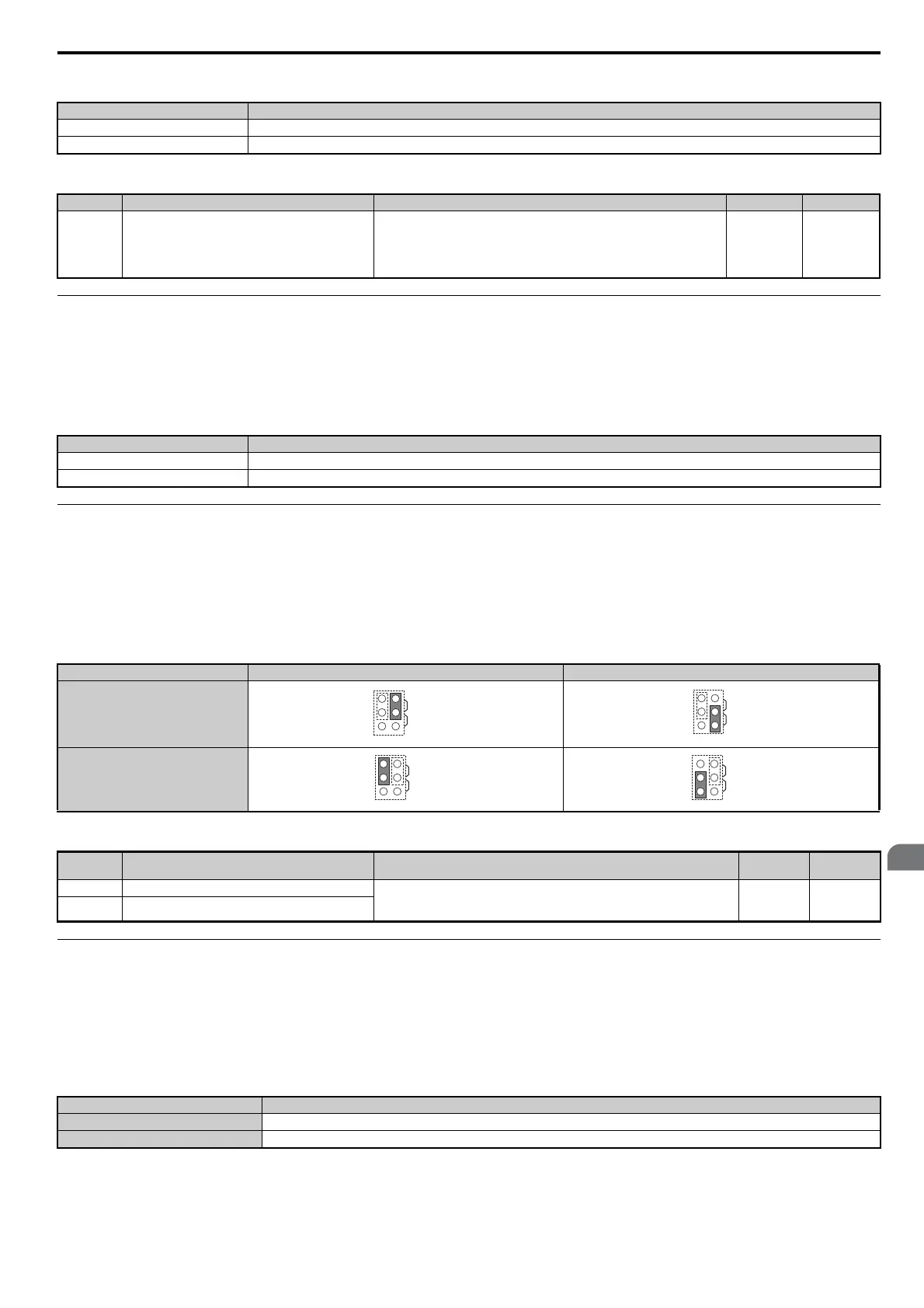
u Terminal AM/FM Signal Selection
The signal type for terminals AM and FM can be set to either voltage or current output using jumper S5 on the terminal
board as explained in Table 3.16. When changing the setting of jumper S5, parameters H4-07 and H4-08 must be set
accordingly. The default selection is voltage output for both terminals. Refer to Switches and Jumpers on the Terminal
Board on page 64 for locating jumper S5.
Table 3.16 Jumper S5 Settings
Table 3.17 Parameter H4-07, H4-08 Details
u MEMOBUS/Modbus Termination
This drive is equipped with a built in termination resistor for the RS-422/485 communication port. DIP switch S2 enables
or disabled the termination resistor as shown in Table 3.18. The OFF position is the default. The termination resistor
should be placed to the ON position when the drive is the last in a series of slave drives. Refer to Switches and Jumpers
on the Terminal Board on page 64 for locating switch S2.
Table 3.18 MEMOBUS/Modbus Switch Settings
Note: Refer to MEMOBUS/Modbus Communications on page 445 for details on MEMOBUS/Modbus.
Setting Description
V (left position) Voltage input (-10 to +10 V, or 0 to +10 V)
I (right position) (default) Current input (4 to 20 mA or 0 to 20 mA): default setting
No. Parameter Name Description Setting Range Default
H3-09 Terminal A2 signal level selection
Selects the signal level for terminal A2.
0: 0 to 10 Vdc
1: -10 to 10 Vdc
2: 4 to 20 mA
3: 0 to 20 mA
0 to 3 2
Setting Description
AI (lower position) (default) Analog input for the function selected in parameter H3-06
PTC (upper position) PTC input. Parameter H3-06 must be set to E (PTC input)
Voltage Output Current Output
Terminal AM
Terminal FM
No. Parameter Name Description
Setting
Range
Default
Setting
H4-07 Terminal AM signal level selection 0: 0 to 10 Vdc
1: -10 to 10 Vdc
2: 4 to 20 mA
0 to 2 0
H4-08 Terminal FM signal level selection
S2 Position Description
ON Internal termination resistor ON
OFF Internal termination resistor OFF (default setting)
AMFM
V
I
AMFM
V
I
AMFM
V
I
AMFM
V
I