244 YASKAWA ELECTRIC SIEP C710616 30B YASKAWA AC Drive T1000A Technical Manual
5.10 o: Operator Related Settings
5.10 o: Operator Related Settings
These parameters are for controlling the various functions, features, and display of the digital operator.
u o1: Digital Operator Display Selection
These parameters determine how data appears on the operator display.
n
o1-01: Drive Mode Unit Monitor Selection
When the drive is powered up, the monitor selected in parameter o1-02 appears first on the display. If o1-02 is set to 5,
o1-01 can be used to change the content of this monitor.
When using an LED operator, pressing the up arrow key will display the following data: speed reference → rotational
direction → output speed → output current → o1-01 selection.
Parameter o1-01 lets the user select the content of the last monitor in this sequence. There is no effect like this on an LCD
operator.
n
o1-02: User Monitor Selection after Power Up
Selects which monitor parameter is displayed upon power up. This is done by entering the 1 part of U1-. Certain
monitors are not available in some control modes. Refer to U: Monitor Parameters on page 263 for a list of monitors.
Setting 1: Frequency reference (U1-01)
Setting 2: Motor direction
Setting 3: Output frequency (U1-02)
Setting 4: Output current (U1-03)
Setting 5: User-selected monitor (set by o1-01)
n o1-03: Digital Operator Display Selection
Sets the units used to display the frequency reference and output frequency. Set o1-03 to 3 for user-set units, then set
parameters o1-10 and o1-11.
Setting 0: 0.01 Hz units
Setting 1: 0.01% units (100% = max. output frequency)
Setting 2: r/min units (calculated by the max output frequency and the no. of motor poles)
Setting 3: User-set units (use o1-10, o1-11)
Set the value use for the maximum frequency reference to o1-10. The placement of the decimal point in this number
should be set to o1-11.
For example, to have the maximum output frequency displayed as “100.00”, set the o1-10 = 1000 and o1-11 = 2 (i.e.,
1000 with 2 decimal points).
Note: 1. Parameter o1-03 allows the programmer to change the units used in the following parameters and monitors:
x U1-01: frequency reference
x U1-02: output frequency
x U1-05: motor speed
x U1-16: output frequency after softstarter (accel/decel ramp generator)
x d1-01 to d1-17: frequency references
2. Setting o1-03 to 2 requires that the number of motor poles be entered to E2-04, E4-04, and E5-04.
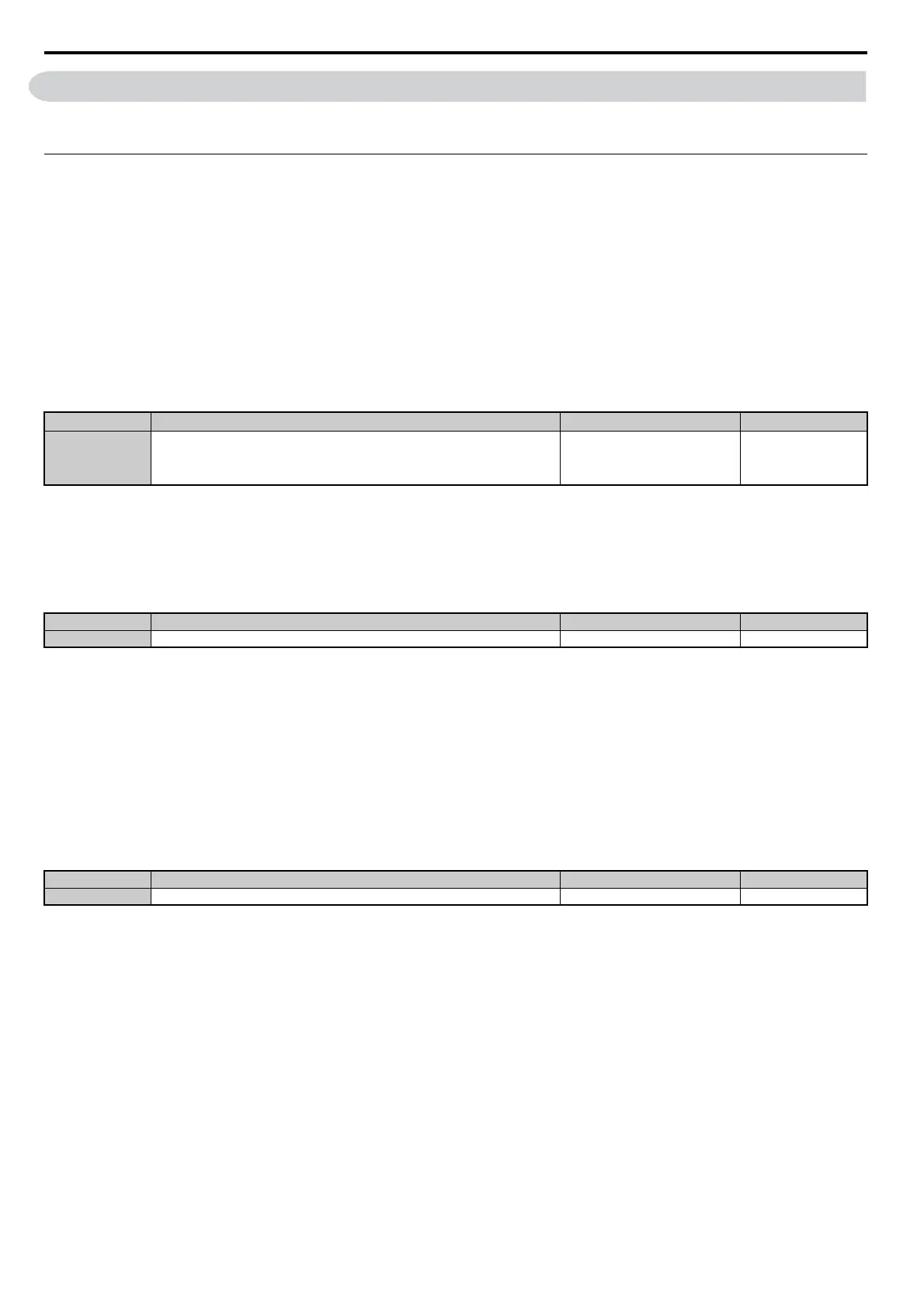
No.
<1> U2- and U3- parameters cannot be selected.
Name Setting Range Default
o1-01 Drive Mode Unit Monitor Selection
104 to 905
U1-04 (Control Mode) to
U9-05 (Motor Residual Voltage
(Synchronous Operation))
<1>
106 (U1-06)
No. Name Setting Range Default
o1-02 User Monitor Selection after Power Up 1 to 5 1
No. Name Setting Range Default
o1-03 Digital Operator Display Selection 0 to 3 Determined by A1-02