4.6 Auto-Tuning
YASKAWA ELECTRIC SIEP C710616 30B YASKAWA AC Drive T1000A Technical Manual 97
Start-Up Programming
& Operation
4
u Parameter Settings during Inertia and Speed Control Loop Auto-Tuning: T3
These tuning methods apply a sine wave test signal to the system. By the measuring the response the drive estimates the
system inertia. It automatically sets parameters listed in Table 4.12.
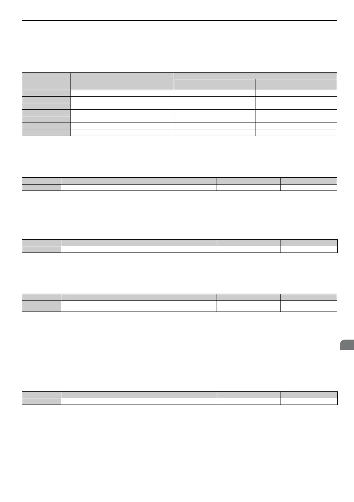
Table 4.12 Parameters Adjusted by Inertia and Speed Loop Auto-Tuning
n T3-01: Inertia Tuning Frequency Reference
Sets the frequency of the test signal applied to the motor during Inertia Tuning. Although this setting rarely needs to be
changed, increasing the value may be beneficial when working with high inertia loads.
n
T3-02: Inertia Tuning Reference Amplitude
Enter the amplitude of the test signal applied to the motor during Inertia Tuning. Although this setting rarely needs to be
changed, try decreasing the value if the load inertia is too large and causes problems during Inertia Tuning. If a fault
occurs when T3-01 is set to low value, the situation may be remedied by adjusting T3-02.
n
T3-03: Motor Inertia
Enter the inertia of the motor. This value is used to determine the load inertia using the test signal response. The default
setting is for a Yaskawa standard motor as listed in the motor inertia table.
Note: This value's number of decimal places depends on the drive model and the Heavy/Normal duty selection in parameter C6-01.
The value will have four decimal places (0.0001 kgm
2
) if the drive is set for a Maximum Applicable Motor Capacity up to 37 kW
(refer to Table A.2 and Table A.3) and three decimal places (0.001 kgm
2
) if the set Maximum Applicable Motor Capacity is 37
kW to 90 kW.
n T3-04: ASR Response Frequency
Sets the response frequency (reciprocal of the step response time constant) of the system or the connected machine. The
drive uses this value and the load inertia to fine-tune the speed control loop gain (C5-01, ASR Gain 1). Oscillation may
result if the value input here is higher than the actual response frequency of the system.
Parameter Description
T1-01 or T2-01
8
Inertia Tuning
9
Speed Control Loop (ASR) Tuning
C5-01 (C5-21) ASR Proportional Gain 1 N/A YES
C5-17 (C5-37) Motor Inertia YES YES
C5-18 (C5-38) Motor Inertia Ratio YES YES
S6-02 Motor Acceleration Time for Inertia Calculations YES YES
S6-03 Load Inertia Ratio YES YES
n5-02 Motor Acceleration Time YES YES
n5-03 Feed Forward Control Ratio Gain YES YES
No. Name Setting Range Default
T3-01 Inertia Tuning Frequency Reference 0.1 to 20.0 Hz 3.0 Hz
No. Name Setting Range Default
T3-02 Inertia Tuning Reference Amplitude 0.1 to 10.0 rad 0.5 rad
No. Name Setting Range Default
T3-03 Motor Inertia
0.0001 to 600.00 kgm
2
Depending on o2-04, C6-01, and
E5-01
No. Name Setting Range Default
T3-04 ASR Response Frequency 0.1 to 50.0 Hz 10.0 Hz