5.2 b: Application
YASKAWA ELECTRIC SIEP C710616 30B YASKAWA AC Drive T1000A Technical Manual 119
Parameter Details
5
Figure 5.12
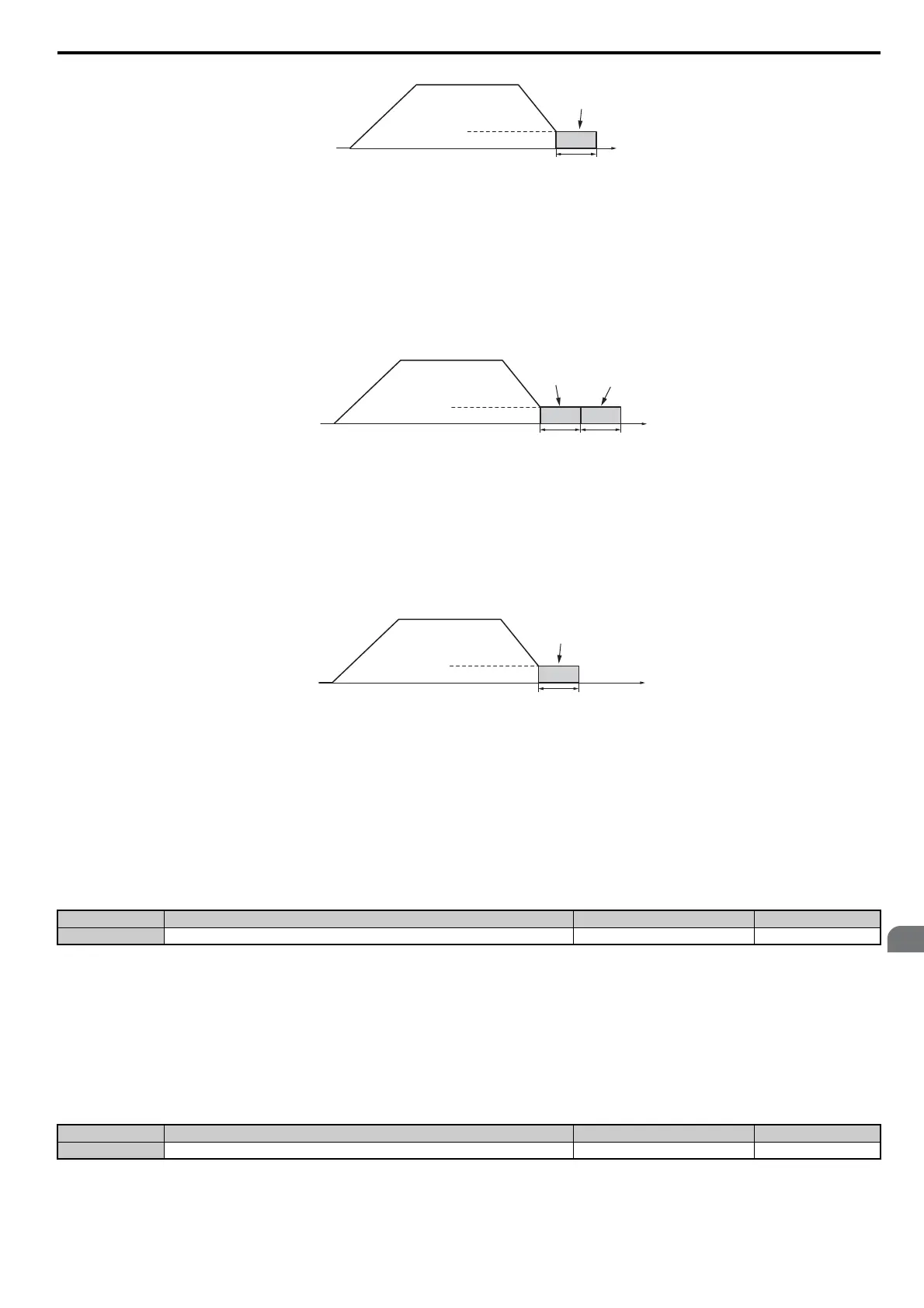
Figure 5.12 DC Injection Braking at Stop for V/f, V/f w/PG and OLV
Note: If b2-01 is set to a smaller value than parameter E1-09 (minimum frequency), then DC Injection Braking will begin as soon as
the frequency falls to the value set to E1-09.
OLV/PM and AOLV/PM (A1-02 = 5, 6)
For these control modes, parameter b2-01 sets the starting frequency for Short-Circuit Braking at stop. Once the output
frequency falls below the setting of b2-01, Short-Circuit Braking is enabled for the time set in parameter b2-13. If DC
Injection Braking time is enabled at stop, then DC Injection Braking is performed for the time set in b2-04 after Short-
Circuit Braking is complete.
Figure 5.13
Figure 5.13 Short-Circuit Braking at Stop in OLV/PM and AOLV/PM
Note: If b2-01 is set to a smaller value than parameter E1-09 (minimum frequency), then DC Injection Braking will begin as soon as
the frequency falls to the value set to E1-09.
CLV and CLV/PM (A1-02 = 3, 7)
For these control modes, parameter b2-01 sets the starting frequency for Zero Speed Control (not position lock) at stop.
Once the output frequency falls below the setting of b2-01, Zero Speed Control is enabled for the time set in parameter
b2-04 if b1-05 = 0.
Figure 5.14
Figure 5.14 Zero Speed Control at Stop in CLV and CLV/PM
Note: If b2-01 is set to lower than the minimum frequency (E1-09), then Zero Speed Control begins at the frequency set to E1-09.
n b2-02: DC Injection Braking Current
Sets the DC Injection Braking current as a percentage of the drive rated current. If set larger than 50%, the carrier
frequency is automatically reduced to 1 kHz.
If one of the multi-function input terminals is set for DC Injection Braking 1 (H1- = 59) and that terminal is
activated, then the drive will use the current level set in b2-02 to perform DC Injection Braking.
The level of DC Injection Braking current affects the strength of the magnetic field attempting to lock the motor shaft.
Increasing the current level will increase the amount of heat generated by the motor windings. This parameter should
only be increased to the level necessary to hold the motor shaft.
n
b2-03: DC Injection Braking Time at Start
Sets the time of DC Injection Braking (Zero Speed Control when in CLV and CLV/PM) at start. Used to stop a coasting
motor before restarting it or to apply braking torque at start. Disabled when set to 0.00 s.
Note: Before starting an uncontrolled rotating motor (e.g., a fan motor driven by windmill effect), DC Injection or Speed Search should
be used to either stop the motor or detect its speed before starting it. Otherwise motor stalling and other faults can occur.
No. Name Setting Range Default
b2-02 DC Injection Braking Current 0 to 100% 50%
No. Name Setting Range Default
b2-03 DC Injection Braking Time at Start 0.00 to 10.00 s 0.00 s
Output
frequency
Time
b2-04
DC Injection
Braking
E1-09 Min. Frequency
b2-01 Zero Speed Level
Output
frequency
Time
DC Injection
Braking
b2-04b2-13
Short Circuit
Braking
E1-09 Min. Frequency
b2-01 Zero Speed Level
Output
frequency
Time
Zero Speed
Control
b2-04
E1-09 Min. Frequency
b2-01 Zero Speed Level

 Loading...


