6.4 Fault Detection
YASKAWA ELECTRIC SIEP C710616 30B YASKAWA AC Drive T1000A Technical Manual 281
Troubleshooting
6
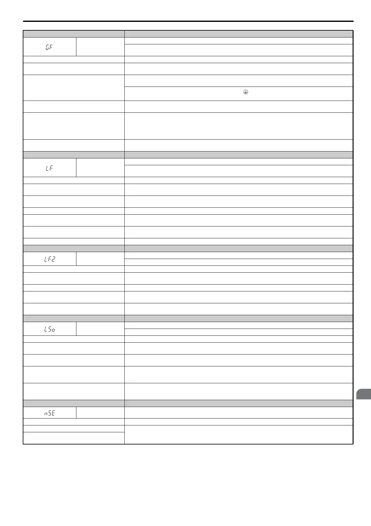
Digital Operator Display Fault Name
GF
Ground Fault
• A current short to ground exceeded 50% of rated current on the output side of the drive.
• Setting L8-09 to 1 enables ground fault detection.
Cause Possible Solution
Motor insulation is damaged.
• Check the insulation resistance of the motor.
• Replace the motor.
A damaged motor cable is creating a short circuit.
• Check the motor cable.
• Remove the short circuit and turn the power back on.
• Check the resistance between the cable and the ground terminal .
• Replace the cable.
The leakage current at the drive output is too high.
• Reduce the carrier frequency.
• Reduce the amount of stray capacitance.
The drive started to run during a current offset fault or
while coasting to a stop.
• The value set exceeds the allowable setting range while the drive automatically adjusts the current offset (this happens only
when attempting to restart a PM motor that is coasting to stop).
• Enable Speed Search at start (b3-01 = 1).
• Perform Speed Search 1 or 2 (H1- = 61 or 62) via one of the external terminals.
Note: Speed Search 1 and 2 are the same when using PM OLV.
Hardware problem.
Replace either the control board or the entire drive. For instructions on replacing the control board, contact Yaskawa or your
nearest sales representative.
Digital Operator Display Fault Name
LF
Output Phase Loss
• Phase loss on the output side of the drive.
• Phase Loss Detection is enabled when L8-07 is set to 1 or 2.
Cause Possible Solution
The output cable is disconnected.
• Check for wiring errors and ensure the output cable is connected properly.
• Correct the wiring.
The motor winding is damaged.
• Check the resistance between motor lines.
• Replace the motor if the winding is damaged.
The output terminal is loose. Apply the tightening torque specified in this manual to fasten the terminals. Refer to Wire Size on page 62.
The rated current of the motor being used is less than 5%
of the drive rated current.
Check the drive and motor capacities.
An output transistor is damaged.
Replace either the control board or the entire drive. For instructions on replacing the control board, contact Yaskawa or your
nearest sales representative.
A single-phase motor is being used. The drive cannot operate a single phase motor.
Digital Operator Display Fault Name
LF2
Output current imbalance
One or more of the phases in the output current is lost.
Cause Possible Solution
Phase loss has occurred on the output side of the drive.
• Check for faulty wiring or poor connections on the output side of the drive.
• Correct the wiring.
Terminal wires on the output side of the drive are loose. Apply the tightening torque specified in this manual to fasten the terminals. Refer to Wire Size on page 62.
The output circuit is damaged.
Replace either the control board or the entire drive. For instructions on replacing the control board, contact Yaskawa or your
nearest sales representative.
Motor impedance or motor phases are uneven.
• Measure the line-to-line resistance for each motor phase. Ensure all values are the same.
• Replace the motor.
Digital Operator Display Fault Name
LSo
LSo Fault <2>
Pull-out was detected while operating at low speed.
Cause Possible Solution
The incorrect motor code has been entered.
Enter the correct motor code for the PM motor being used into E5-01.
For special-purpose motors, enter the correct data to all E5 parameters according to the test report provided for the motor.
The load is too heavy.
• Reduce the load.
• Replace the drive with a larger model.
The drive incorrectly detected the position of the motor
poles.
• Make sure some external force is not rotating the motor at start.
• Enable Speed Search Selection at start. (b3-01 = 1)
• If the value displayed in U6-57 is lower than 819, then set the polarity judge current (n8-84) higher than the default value.
Values set to parameters L8-93, L8-94, and L8-95 are
incorrect.
• Increase the value set to L8-93.
• Increase the value set to L8-94.
• Increase the value set to L8-95.
Digital Operator Display Fault Name
nSE CANopen Node Setup Error
Cause Possible Solution
The node setup terminal closed during run.
Stop the drive when using the node setup function.
A run command was issued while the node setup
function was active.

 Loading...


