8.4 Option Card Installation
YASKAWA ELECTRIC SIEP C710616 30B YASKAWA AC Drive T1000A Technical Manual 341
Peripheral Devices &
Options
8
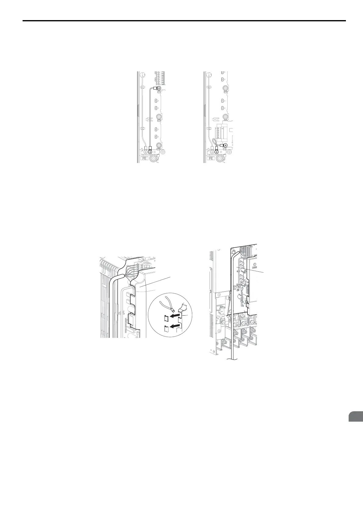
3. Connect one of the lead lines using one of the screws to the ground terminal.
Some option cards come with several different lead lines for connecting the card to the drive. Select the lead line
with the most appropriate length.
Note: There are only two screw holes on the drive for ground terminals. If three option cards are connected, two of the lead lines will
need to share the same ground terminal.
Figure 8.3
Figure 8.3 Connecting the Ground Terminal
4. Wire the option card to the terminal block on the option card.
For wiring instructions, refer to the manual delivered with the option card.
When installing option cards to drive models CIMR-T2A0004 through 0040 and to models CIMR-T4A0002
through 0023, the cables connected to the option might need to be routed through the top cover to the outside.
In this case, cut out the perforated openings on the left side of the drive top cover. Make sure no sharp edges are
left that may damage the cable.
Models CIMR-T2A0056 through 0415 and 4A0031 through 0362 have enough space to keep all wiring inside
the unit.
Figure 8.4
Figure 8.4 Wiring Space
5. Place the front cover and digital operator back onto the drive.
Note: Leave enough space when wiring so that the front cover can be easily reattached. Make sure no wires get caught between the
front cover and the drive.
A – Cable through hole
(CIMR-T2A0004 to 0040, 4A0002 to 0023)
B – Space for wiring
(CIMR-T2A0056 to 0415, 4A0031 to 0362)
B
A