2000-OSM, F1 8-3
SAMPLE VALVE REPAIR
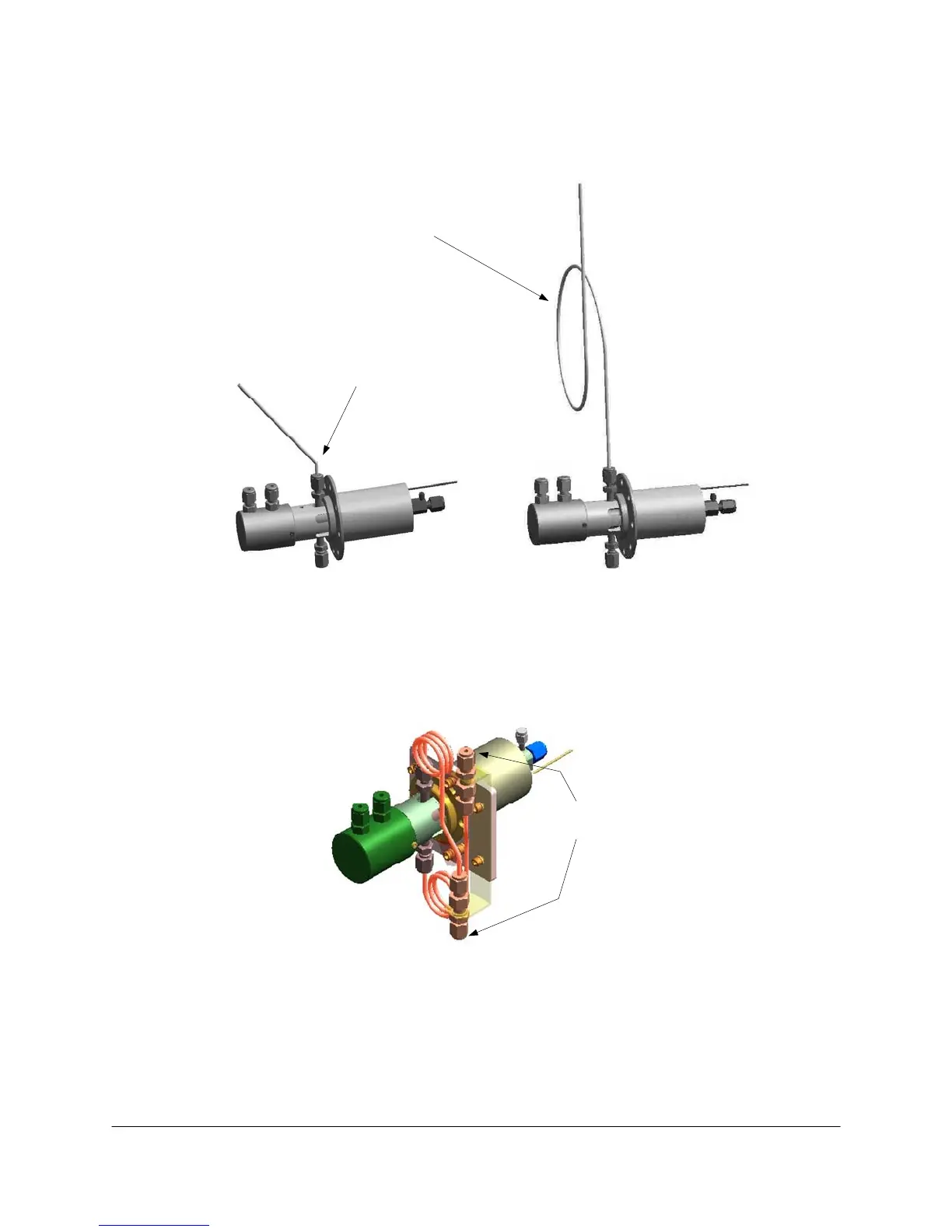
The Liquid Sample Valve (LSV) utilizes two different connection methods for the sample lines. Earlier
analyzers had these sample lines connected directly to the LSV, as shown in Figure 8-2.
INCORRECT CORRECT
Putting a loop in the tubing or using flexible
hose reduces any sideways force at the
connection.
Forcing the tubing into a position can
exert a sideways force at the
connection, causing valve leakage.
Figure 8-2. LSV CONNECTION METHODS, EARLY ANALYZERS
New analyzers have the sample lines connected to a mounting plate attached to the LSV's mounting
flange, as shown in Figure 8-3.
Customer
Connections
Figure 8-3. LSV CONNECTION METHODS, NEW ANALYZERS
You must take extreme care to avoid having the sample lines exert force on the sample connections
of the Liquid Sample Valve. For example, if stiff 1/4-inch tubing or heat-traced lines are bent into
position and attached to the valve or to the mounting plate, the force will cause premature failure of
the valve and possibly bend the stem. A loop of 1/8-inch tubing or a flex hose is recommended
between the valve and the sample line (this may be insulated if necessary). Figure 8-2 illustrates the
incorrect and correct connection methods.