2000-OSM, F1 8-5
Disassembly on the Analyzer
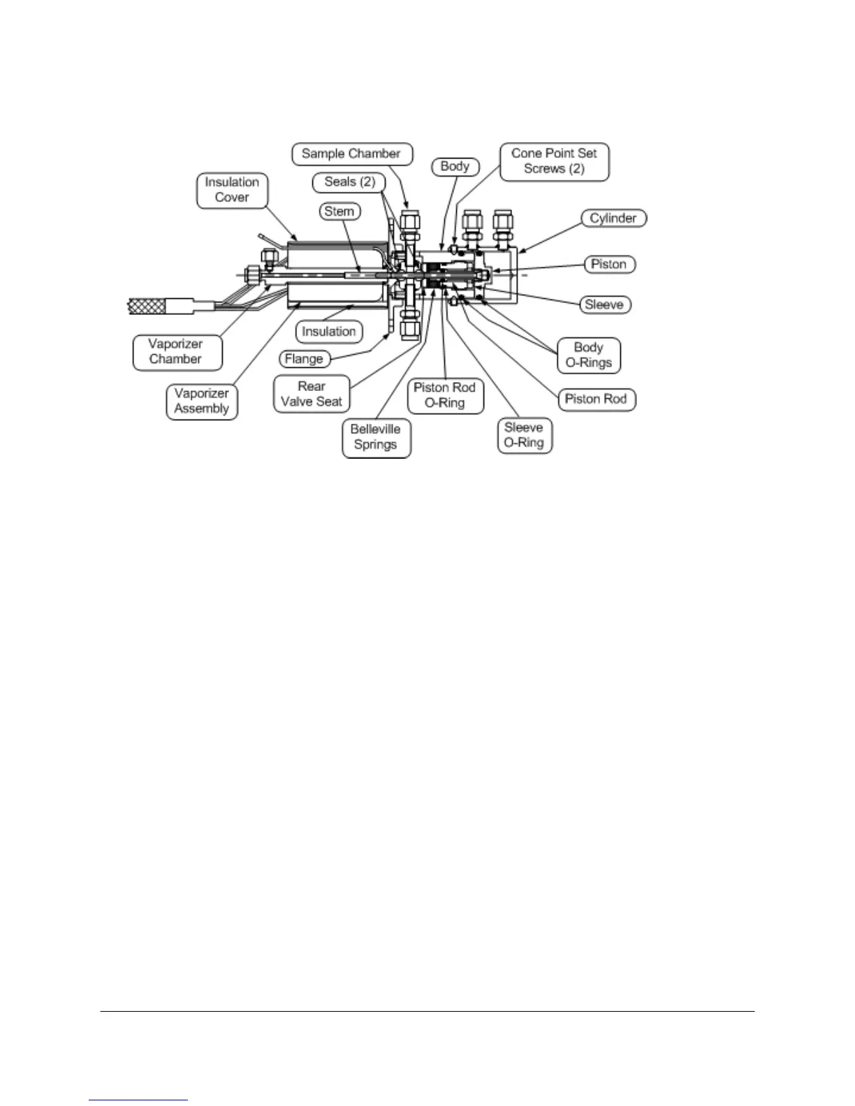
See Figure 8-4 for typical sample valve component location.
Figure 8-4. LIQUID SAMPLE VALVE COMPONENT LOCATION
1. Stop the analysis at the end of a cycle.
2. Turn off power, carrier, sample, and air to the analyzer.
3. Open the isothermal oven door.
4. Label all tubing connections to the Liquid Sample Valve.
5. Disconnect all tubing from the Liquid Sample Valve.
6. Mark the analyzer and flange to ensure the flange is reinstalled in the correct orientation.
7. Remove the four screws holding the flange to the side of the analyzer.
8. Separate the LSV from the analyzer, being careful not to stress the vaporizer assembly cabling.
9. Remove the insulation cover and insulation from around the vaporizer assembly.
10. Remove the four screws that retain the two parts of the vaporizer assembly.
11. Separate the vaporizer assembly from the vaporizer chamber.
12. Remove the two cone point set screws from the cylinder.
13. Slide the cylinder off the piston and body.
14. Mark on the body the location of the sample chamber.
15. Using a hex key wrench, rotate the sleeve counterclockwise until it is loose.
16. Unscrew the body from the flange and vaporizer chamber.