2000-OSM, F2 8-43
Removing the EPC Control Assembly
CAUTION
Be sure that the EPC Control Assembly has cooled to ambient temperature
(approximately one hour) before proceeding.
1. Perform the “Preparation” procedure.
2. Open the Control Housing access panel.
3. Remove the two screws holding the EPC cover and remove the cover panel.
4. Remove the four screws holding the Purge Air Panel in place and carefully pull the panel
forward and down.
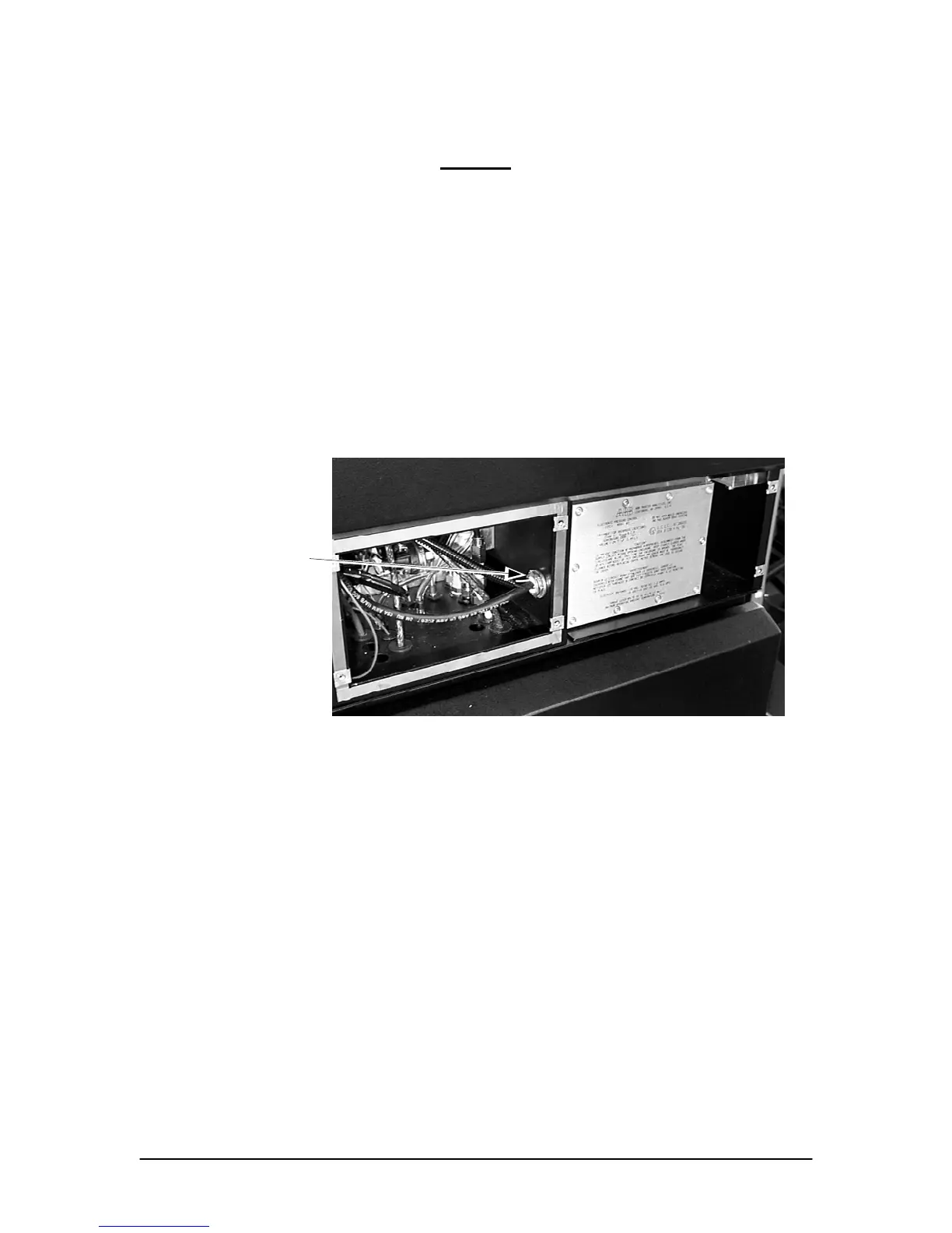
5. On the side wall behind the Purge Air Panel remove the lock nut on the pipe nipple which
retains the EPC Panel cables (see Figure 8-20).
Lock Nut
Figure 8-20. EPC PANEL CABLE LOCK NUT
6. Open the isothermal oven door.
7. In the isothermal oven, disconnect the EPC feedthrough tube nuts.
8. In the isothermal oven, unscrew the feedthroughs and pull them downward approximately
0.5 inches; it is not necessary to remove them completely.
9. Open the Controller front door to gain access to the backplane board.
10. At the left side of the backplane r board, disconnect the EPC Control Assembly cable
from J44.
11. On the EPC Multibus PCB in the card cage, disconnect the EPC Control Assembly cable
from J43 (near the bottom of the PCB).
12. In the Control Housing access area, unplug the alarm switches from the backplane board
13. Unscrew the alarm switches from the manifold.