8-56 2000-OSM, F1
• Revision E or later: the shunt goes between pins 1 and 2 for normal operation (a Chroma I/O
PCB dedicated to a single detector amplifier); the shunt is installed between pins 2 and 3 when
the outputs of two detector amplifiers are applied to a single Chroma I/O PCB.
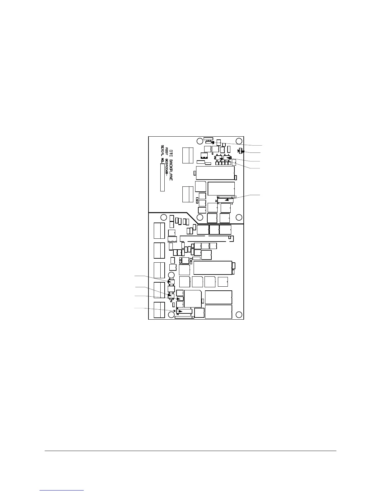
DTC Backplane PCB
The Digital Temperature Controller (DTC) PCB has eight jumpers and one switch to set up (see
Figure 8-28 for location).
Switch SW1 is used to save configuration information to protected memory. Its use is described in
“DIGITAL TEMPERATURE CONTROLLER” in Section 4, by the statement “Hold down the switch on
the DTC Backplane PCB.”
JP3
JP1
JP4
JP5
JP6
JP2
JP3
SW1
SW1
J3
J2
Figure 8-28. DTC BACKPLANE PCB SWITCH AND JUMPER LOCATIONS
Jumpers J2 and J3 are T-Rating jumpers. The jumper shunts must be installed exactly as shown
below to ensure the temperature control operates properly. If they are set incorrectly, T-Rating
disagreement alarms will result (0 = no jumper; 1 = jumper installed).
Pins T5 T4A T4 T3B T3 T2C T2 T1
1-2 0 1 0 1 0 1 0 1
3-4 0 0 1 1 0 0 1 1
5-6 0 0 0 0 1 1 1 1
7-8 Shunts installed in these positions Zone 1
9-10 allow set points (for the respective Zone 2
11-12 zones) to be above the T-Rating, Zone 3
13-14 for explosion proof zones only. Zone 4
15-16 Zone 5