2000-OSM, F1 4-66
REMOTE GC OPERATION OPTION
The analyzer can operate with other ABB GCC front panels. To implement this option requires the
following changes to the analyzer: an optional PCB and several changes in wiring connections and
switch settings. This section of the manual explains how to prepare the analyzer for remote operation
and how to operate it in this configuration.
LO COMM PCB Setup
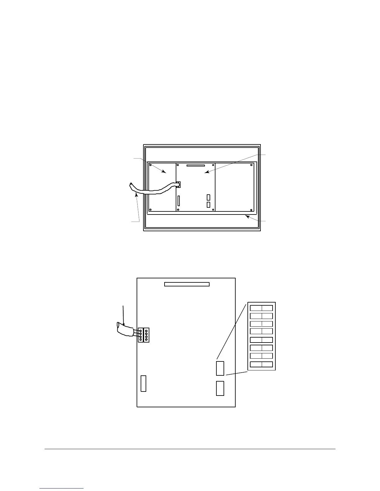
The optional Local Communications Module (LO COMM) PCB provides the remote access for the
analyzer. The analyzer has this board, mounted on the Front Panel PCB located inside the GCC
(see Figure 4-56), only when remote operation is specified. The LO COMM PCB connections
terminate at TB4 in the GCC cabinet.
FRONT PANEL
PCB
LO COMM
CABLE
LO COMM
PCB
DISPLAY
PANEL
Figure 4-56. LOCATION OF LO COMM PCB
Each LO COMM PCB has a unique address to ensure positive communication. Switch SW1, an
eight-position dip switch on the LO COMM PCB (see Figure 4-57), sets this address.
LO COMM
CABLE
SW1
SW2
1
2
3
4
5
0
OFF
6
7
8
1
ON
Figure 4-57. LOCATION OF LO COMM PCB SWITCHES