6-42 2000-OSM, F1
6. If the selected alarm has "(Expanded)" after the alarm name, the alarm has subordinate
indicators. To view these subordinates, cursor to the desired alarm line and press the F2
(Expand Mask) soft key.
7. On the expanded alarm screen, repeat steps 4 and 5 to change a specific alarm's output.
8. Press the F1 (Exit) soft key to return to the Control Parameters screen.
9. Press the F2 (Exit and Update) soft key to save the new alarm data, or press the F1 (Escape) soft
key to retain the original data.
10. Press the F1 soft key as necessary to return to the Background screen.
Alarm Common Output Connections
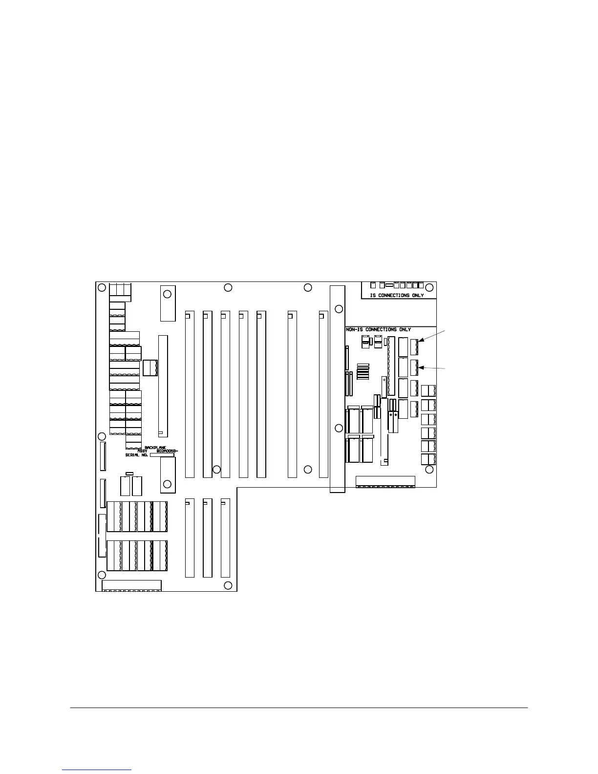
You can view analyzer alarms at the customer's alarm indicator when this indicator is connected to
Hardware Alarm connector J111A and Software Alarm connector J111B on the GCC Backplane PCB
(see Figure 6-22).
TB1
J1A
J1B
1 2 3 4 5 6
J111A
1
1 2 3 4 5 6
J111A
HARDWARE
ALARM
1
J111B
J111B
SOFTWARE
ALARM
Figure 6-22. BACKPLANE PCB DIGITAL ALARM CONNECTIONS
Alarm Common Output Checks
When the Common Digital Output Mask screen has "Common DO" selected for a given alarm, an
alarm condition will illuminate the appropriate alarm LED on the GCC Front Panel (Hardware Fault