2000-OSM, F1 6-43
LED or Software Fault LED) and will send an alarm signal to the customer's alarm indicator (when
that indicator is connected to J111A or J111B on the Backplane PCB).
When the Common Digital Output Mask screen has "Masked" selected for a given alarm, no alarm
signals will be generated.
To verify or change the alarm common output settings:
1. On the Background screen press the F1 (Exit to Commands) soft key.
2. On the Commands screen, cursor to MISC. and press the F2 (Control Parameters) soft key.
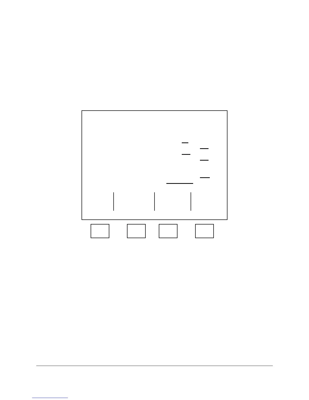
3. On the Control Parameters screen (see Figure 6-23), press the F4 (Common Digital Out. Mask)
soft key.
***** Control Parameters *****
Analyzer Name:
[ABB Analytical GCC ]
Unknown Peak Alarm: No
Yes
Missing Comp Alarm: No Yes
Update Trends on Alarm: No Yes
Auto Update of RF: No Yes
Max RF Variation: 0.000000
Unknown Peak RF: 0.000000
Unknown Peak Units: % ppm
More Below
Exit Alarm Common
Escape and Mask Digital
Update Out Mask
F1 F2 F3 F4
Figure 6-23. CONTROL PARAMETERS SCREEN