8-58 2000-OSM, F1
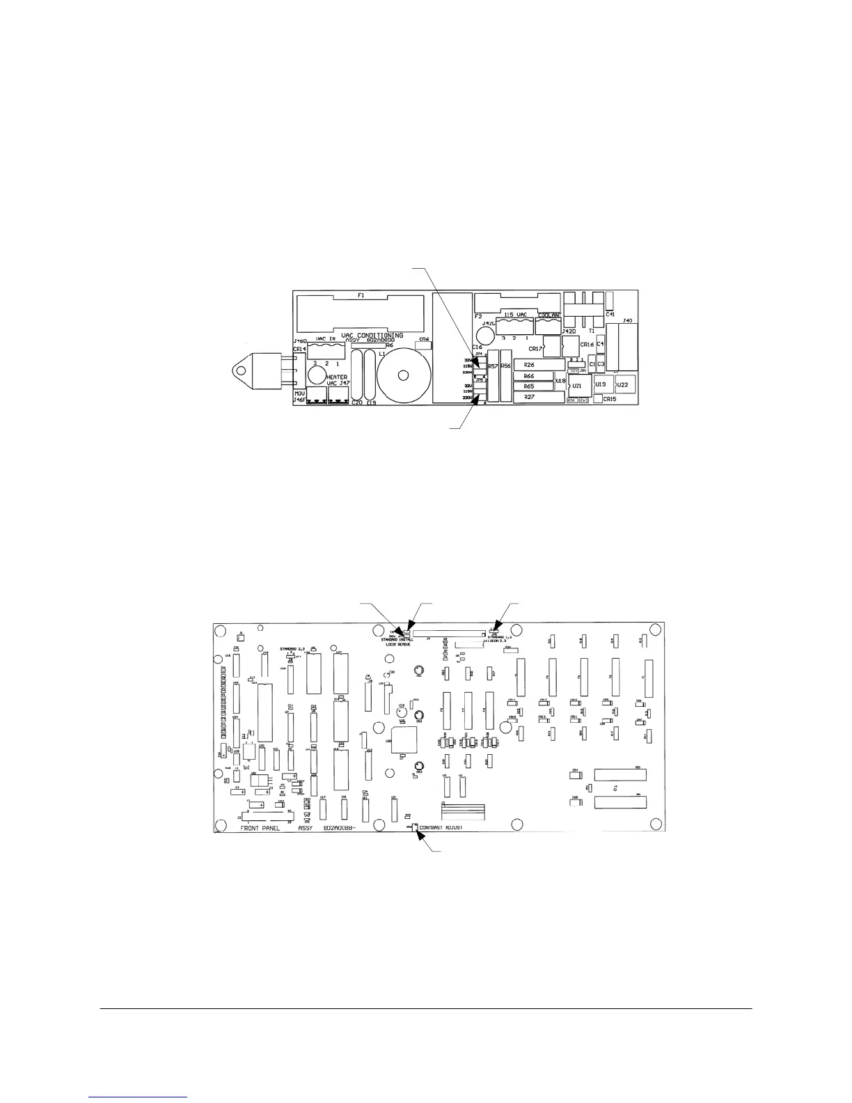
VAC Conditioning PCB
There can be either one or two VAC Conditioning PCBs, depending on the application. Each board
has two jumpers to be set, JP4 and JP5 (see Figure 8-30). These jumpers are set according to the
voltage supplied to the board, as follows (JP4 is the hot side and JP5 is the neutral side):
Applied Voltage JP4 Shunt JP5 Shunt
32 VAC 1-2 1-2
110 VAC 3-4 3-4
220 VAC 5-6 5-6
JP4
JP5
Figure 8-30. VAC CONDITIONING BOARD JUMPER LOCATIONS
Front Panel PCB
There is one adjustment and three jumpers on this board (see Figure 8-31). The adjustment is
potentiometer R56, which is used to set the display contrast for optimum viewing.
JP7 JP6 JP5
R56
Figure 8-31. FRONT PANEL PCB ADJUSTMENT AND JUMPER LOCATIONS
The jumpers relate to the LOCOM option. JP5 has its shunt is between pins 1 and 2 for normal
operation, between pins 2 and 3 for LOCOM installations. JP6 and JP7 have the shunts in place for
normal operation and the shunts removed for LOCOM installations.