2000-OSM, F1 8-61
EPC Multibus PCB
This board has one jumper and one switch to set up (see Figure 8-35).
JP1 is the service diagnostics jumper. For normal operation the shunt is installed between pins 1 and
2. For installation and service the shunt is installed between pins 2 and 3. After installation or
service, the shunt must be reinstalled between pins 1 and 2.
Switch SW1 is used to save configuration information to protected memory. Its use is described in
“ELECTRONIC PRESSURE CONTROL OPTION” in Section 4, by the statement “Hold down the
switch on the Electronic Pressure Control PCB.”
SW1
JP1
Figure 8-35. EPC MULTIBUS PCB JUMPER LOCATION
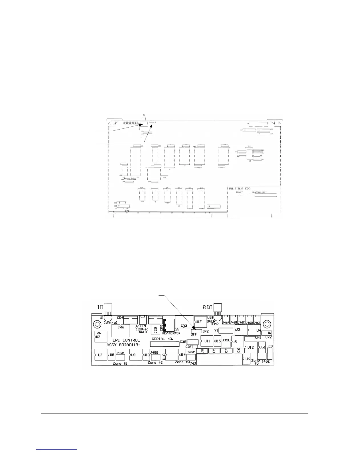
EPC Control PCB
This board has a single jumper, JP2 (see Figure 8-36). For normal operation JP2 has a shunt
between pins 2 and 3. For servicing of the block, the shunt is placed between pins 1 and 2 to turn off
the heater.
JP2
Figure 8-36. EPC CONTROL PCB JUMPER LOCATION