DD+DIS150.06E
Repair and Service
Replacements / Repair Procedures
DOCUMENT CONTROL NOTE:
The controlled version of this document resides on MedNet. Any printed copy of this document is uncontrolled.
Edition 1, Revision 2 CR 30-X Chapter 3.5 / 86
03-2009 Type 5175 / 100/110 Agfa Company Confidential
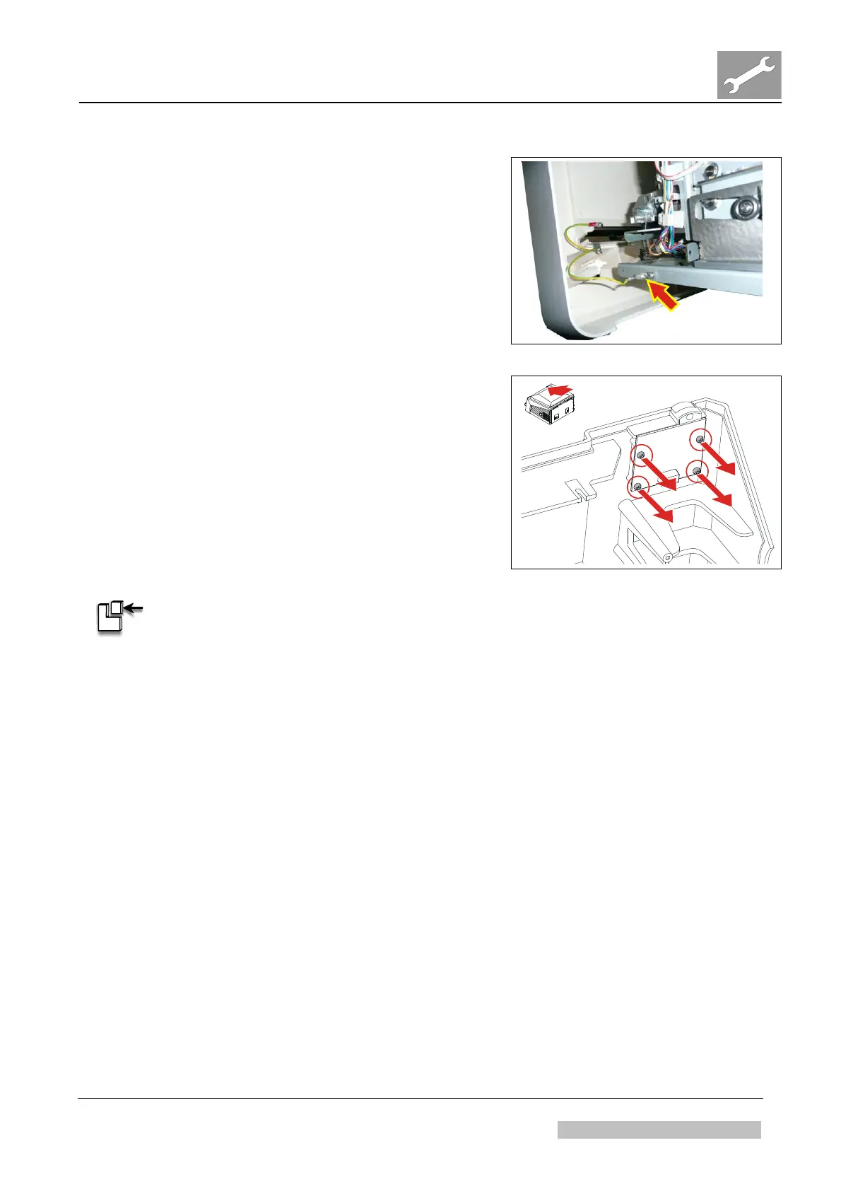
(10) Disconnect ground cable at right hand side.
(11) Remove front cover.
Figure 214
(12) Remove four screws.
(13) Remove the user interface board.
Figure 215
ASSEMBLY:
(1) Mount in reverse order.
Verification:
(1) Switch on the digitizer.
(2) Wait till the status indicator at the digitizer switches to green
(takes approx. 1,5 min.).
(3) Insert cassette with unexposed IP in the digitizer.
(4) At the workstation select examination type “System diagnosis – Flatfield”.
(5) Select “ID” to identify the image: Scanning starts.
(6) Confirm that the image arrives at the workstation.
(7) Reject the image.
Result:
The user interface board is replaced.
 Loading...