DD+DIS150
.06E
Repair and Service
Adjustments and Calibrations
DOCUMENT CONTROL NOTE:
The controlled version of this document resides on MedNet. Any printed copy of this document is uncontrolled.
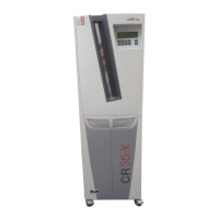
Edition 1, Revision 3 CR 30-X Chapter 3.6 / 4
10-2009 Type 5175 / 100/110 Agfa Company Confidential
1 Overview of Adjustments and Calibrations
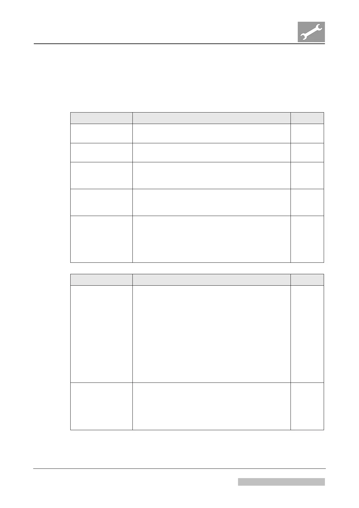
The following tables give an overview of adjustments and calibrations for the digitizer.
Adjustment Type Use Case Section
Drawer Unit
Adjustment
After replacement of the drawer unit 2.1
PMI board carrier
position adjustment
After replacement of the PMT with light collector 2.2
Cassette unit
safety switch
position adjustment
After replacement of cassette unit safety switch 2.3
Cassette edge
sensor position
adjustment
After replacement of cassette edge sensor 2.4
Laser beam
position check and
adjustment
In case of sporadic or persistent errors 10761
or 10767 to identify the possible root cause of
an incorrect laser beam position
To solve errors 10761 or 10767, if an incorrect
laser beam position is the root cause
2.5
Calibration Type Use Case Section
Shading calibration
After replacement of the PMT with light
collector
After replacement of the optic module
After the laser beam position adjustment
Whenever the PMT or light collector have been
removed (e.g. for replacing the slow scan
module).
Whenever stripes in slow scan position are
visible, which cannot be removed by cleaning
of the scan line with the cleaning brush.
3.1
Stall Calibration
After replacement of a motor or mechanical
assembly where a motor with stall detection is
built in
After replacement of the IP handling board (as
this has the motor controllers built in)
During preventive maintenance
3.2
 Loading...