DD+DIS150
.06E
Controls, Connections, and Setup Procedures
DOCUMENT CONTROL NOTE:
The controlled version of this document resides on MedNet. Any printed copy of this document is uncontrolled.
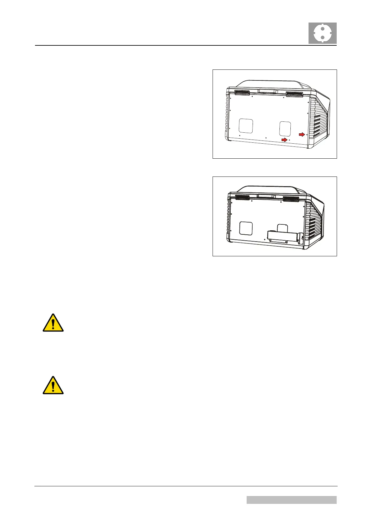
(1) Remove two screws in the rear.
517501wy.cdr
Figure 3
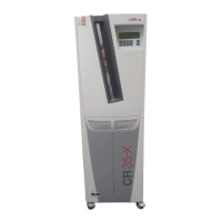
(2) Mount distance holder.
517501wz.cdr
Figure 4
4.2 Connecting the Cables
WARNING:
Using a FWI cable > 4.5 m (15 ft) may lead to unstable or no communication
between digitizer and NX workstation: Retakes possible.
To connect digitizer and control PC, only use a standard 6-pin FWI cable with a max.
length of 4,5 m or 15 ft respectively.
WARNING:
Using different power circles may lead to ground potential differences: In this
case the leakage current via FireWire cable may exceed the limits as defined
by IEC 60601:
Confirm that both, control PC and digitizer are connected to the same ground, e.g.
via multiple socket or UPS.
When connecting digitizer and control PC at two different sockets, installed in the
wall: Inform the hospital technician that digitizer and control PC have to be
connected to the same ground and the same phase.
Edition 1, Revision 5 CR 30-X Chapter 1 / 9
11-2009 Type 5175 / 100/110 Agfa Company Confidential