120 Agilent InfiniiVision 3000 X-Series Oscilloscopes User's Guide
6 Digital Channels
The logic probes are represented by the high- frequency circuit model
shown above. They are designed to provide as much series tip resistance
as possible. Stray tip capacitance to ground is minimized by the proper
mechanical design of the probe tip assembly. This provides the maximum
input impedance at high frequencies.
Probe Grounding
A probe ground is the low-impedance path for current to return to the
source from the probe. Increased length in this path will, at high
frequencies, create large common mode voltages at the probe input. The
voltage generated behaves as if this path were an inductor according to
the equation:
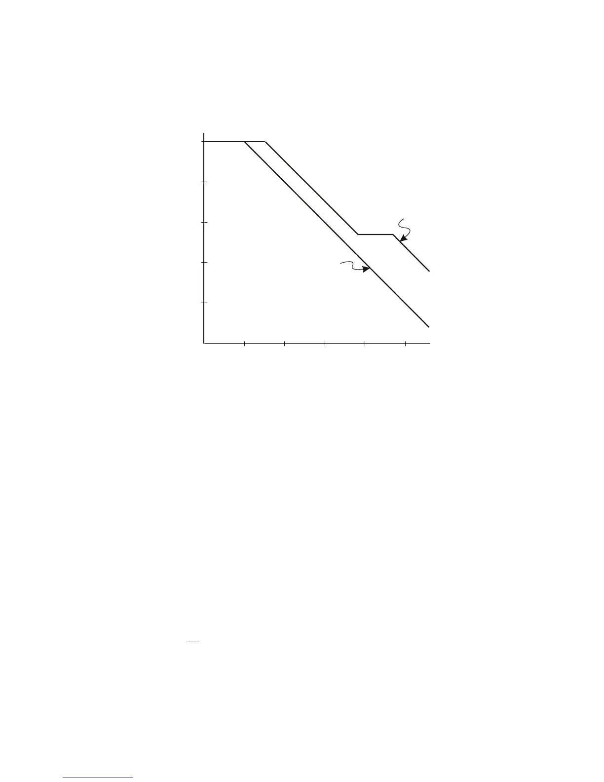
Figure 23 Impedance versus Frequency for Both Probe Circuit Models
100 k
10 k
1 k
100
10
1
10 kHz 100 kHz 1 MHz 10 MHz 100 MHz 1 GHz
High
Frequency
Model
Typical
Model
Frequency
Impedance

 Loading...


