386 Agilent InfiniiVision 3000 X-Series Oscilloscopes User's Guide
25 I2C/SPI Triggering and Serial Decode
Setup for SPI Signals
Serial Peripheral Interface (SPI) signals setup consists of connecting the
oscilloscope to a clock, MOSI data, MISO data, and framing signal, then
setting the threshold voltage level for each input channel, and finally
specifying any other signal parameters.
To set up the oscilloscope to capture SPI signals, use the Signals softkey
which appears in the Serial Decode Menu:
1 Press [Label] to turn on labels.
2 Press [Serial].
3 Press the Serial softkey, turn the Entry knob to select the desired slot
(Serial 1 or Serial 2), and press the softkey again to enable decode.
4 Press the Mode softkey; then, select SPI trigger type.
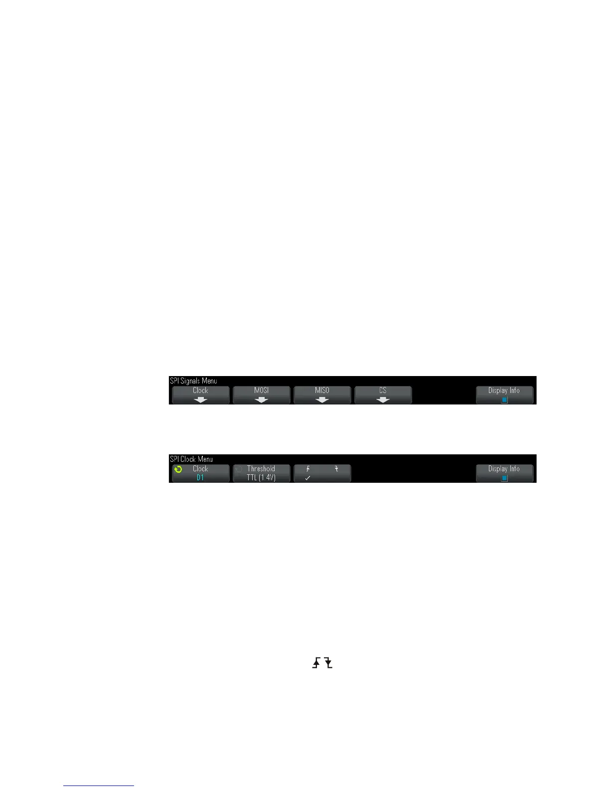
5 Press the Signals softkey to open the SPI Signals Menu.
6 Press the Clock softkey to open the SPI Clock Menu.
In the SPI Clock Menu:
a Press the Clock softkey; then, turn the Entry knob to select the
channel connected to the SPI serial clock line.
The CLK label for the source channel is automatically set.
b Press the Threshold softkey; then, turn the Entry knob to select the
clock signal threshold voltage level.
The threshold voltage level is used in decoding, and it will become
the trigger level when the trigger type is set to the selected serial
decode slot.
c Press the slope softkey ( ) to select rising edge or falling edge for
the selected Clock source.

 Loading...


