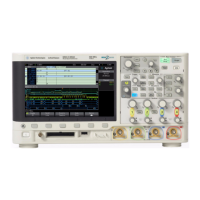
Getting Started 1
Agilent InfiniiVision 3000 X-Series Oscilloscopes User's Guide 41
16. Vertical
controls
The Vertical controls consist of:
• Analog channel on/off keys — Use these keys to switch a channel on
or off, or to access a channel's menu in the softkeys. There is one
channel on/off key for each analog channel.
• Vertical scale knob — There are knobs marked for each
channel. Use these knobs to change the vertical sensitivity (gain) of
each analog channel.
• Vertical position knobs — Use these knobs to change a channel's
vertical position on the display. There is one Vertical Position control
for each analog channel.
•[Label] key — Press this key to access the Label Menu, which lets
you enter labels to identify each trace on the oscilloscope display. See
Chapter 9, “Labels,” starting on page 137.
For more information, see Chapter 3, “Vertical Controls,” starting on
page 63.
17. Analog channel
inputs
Attach oscilloscope probes or BNC cables to these BNC connectors.
With the InfiniiVision 3000 X-Series oscilloscopes, you can set the input
impedance of the analog channels to either 50
Ω or 1 MΩ. See “To
specify channel input impedance" on page 66.
The InfiniiVision 3000 X-Series oscilloscopes also provide the AutoProbe
interface. The AutoProbe interface uses a series of contacts directly
below the channel's BNC connector to transfer information between the
oscilloscope and the probe. When you connect a compatible probe to the
oscilloscope, the AutoProbe interface determines the type of probe and
sets the oscilloscope's parameters (units, offset, attenuation, coupling,
and impedance) accordingly.
18. Demo 2,
Ground, and
Demo 1
terminals
• Demo 2 terminal — This terminal outputs the Probe Comp signal
which helps you match a probe's input capacitance to the
oscilloscope channel to which it is connected. See “Compensate
Passive Probes" on page 34. With certain licensed features, the
oscilloscope can also output demo or training signals on this terminal.
• Ground terminal — Use the ground terminal for oscilloscope probes
connected to the Demo 1 or Demo 2 terminals.
• Demo 1 terminal — With certain licensed features, the oscilloscope
can output demo or training signals on this terminal.

 Loading...


