A20 User Manual (Revision 1.2) Copyright © 2013 Allwinner Technology Co., Ltd. All Rights Reserved. Page 191 / 812
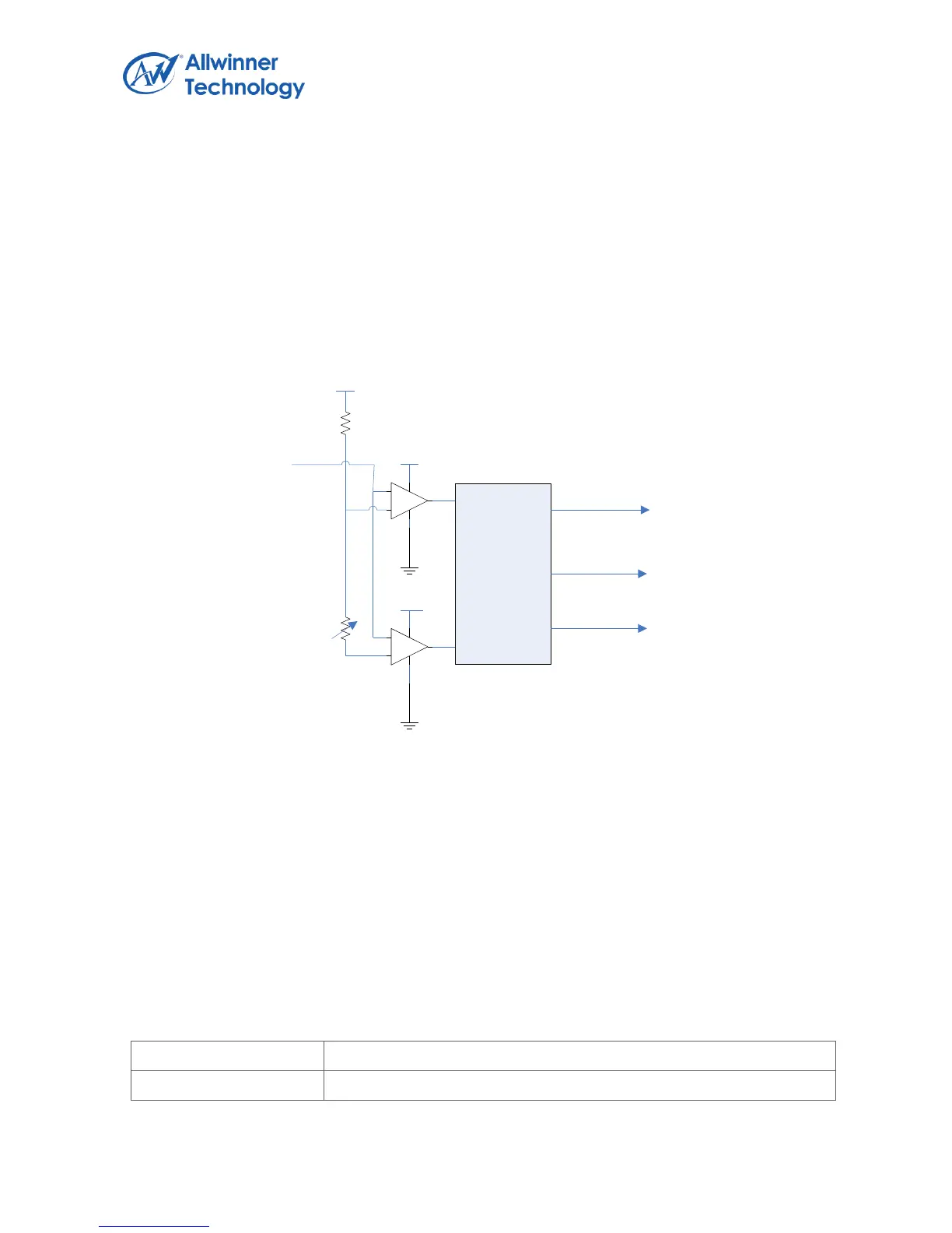
1.14.2. LRADC Block Diagram
The LRADC converted data can by accessed by interrupt and polling method. If software can’t
access the last converted data instantly, the new converted data would update the old one at new
sampling data.
Hold Key and General Key Function Introduction
When ADC_IN Signal change from ADC_REF to 2/3 ADC_REF (Level A), the comparator24 sends
first interrupt to control logic; When ADC_IN Signal changes from 2/3 ADC_REF to certain level
(configurable), the comparator25 gives the second interrupt. If the control Logic gets the first interrupt,
in a certain time range (program can set), doesn’t get second interrupt, it will send hold key interrupt
to the host; If the control Logic get the first interrupt, In a certain time range (program can set), get
second interrupt, it will send key down interrupt to the host; If the control logic only get the second
interrupt, doesn’t get the first interrupt, it will send already hold interrupt to the host.
1.14.3. LRADC Register List