A20 User Manual (Revision 1.2) Copyright © 2013 Allwinner Technology Co., Ltd. All Rights Reserved. Page 606 / 812
6.3.5. SPI Special Requirement
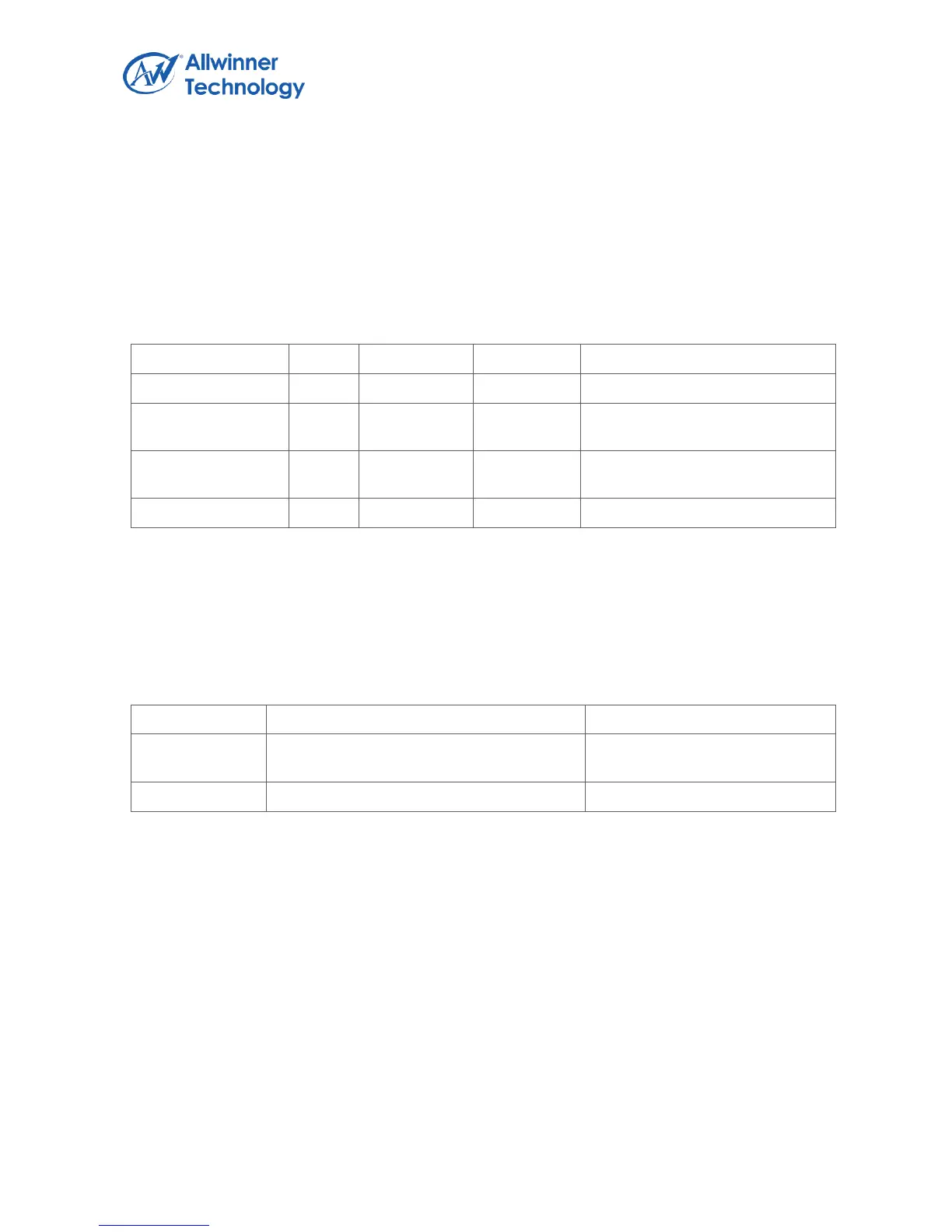
6.3.5.1. SPI PIN LIST
The direction of SPI pin is different in two work modes: Master Mode and Slave Mode.
SPI Master Output Slave Input
Data Signal
SPI Master Input Slave Output
Data Signal
Notes: SPI0 module has four chip select signals and SPI1 module has only one chip select signal for
pin saving.
6.3.5.2. SPI MODULE CLOCK SOURCE AND FREQUENCY
The SPI module uses two clock source: AHB_CLK and SPI_CLK. The SPI_SCLK can in the range
from 3Khz to 100 MHZ and AHB_CLK >= 2xSPI_SCLK.
AHB bus clock, as the clock source of SPI
module