A20 User Manual (Revision 1.2) Copyright © 2013 Allwinner Technology Co., Ltd. All Rights Reserved. Page 482 / 812
Transition Improve Configuration Register
DEFE Video Post Process Luminance
Peaking Configuration 1 Register
DEFE Video Post Process Luminance
Peaking Configuraion 2 Register
DEFE Video Post Process White Level
Extension Configuration Register
DEFE Video Post Process Black Level
Extension Configuration Register
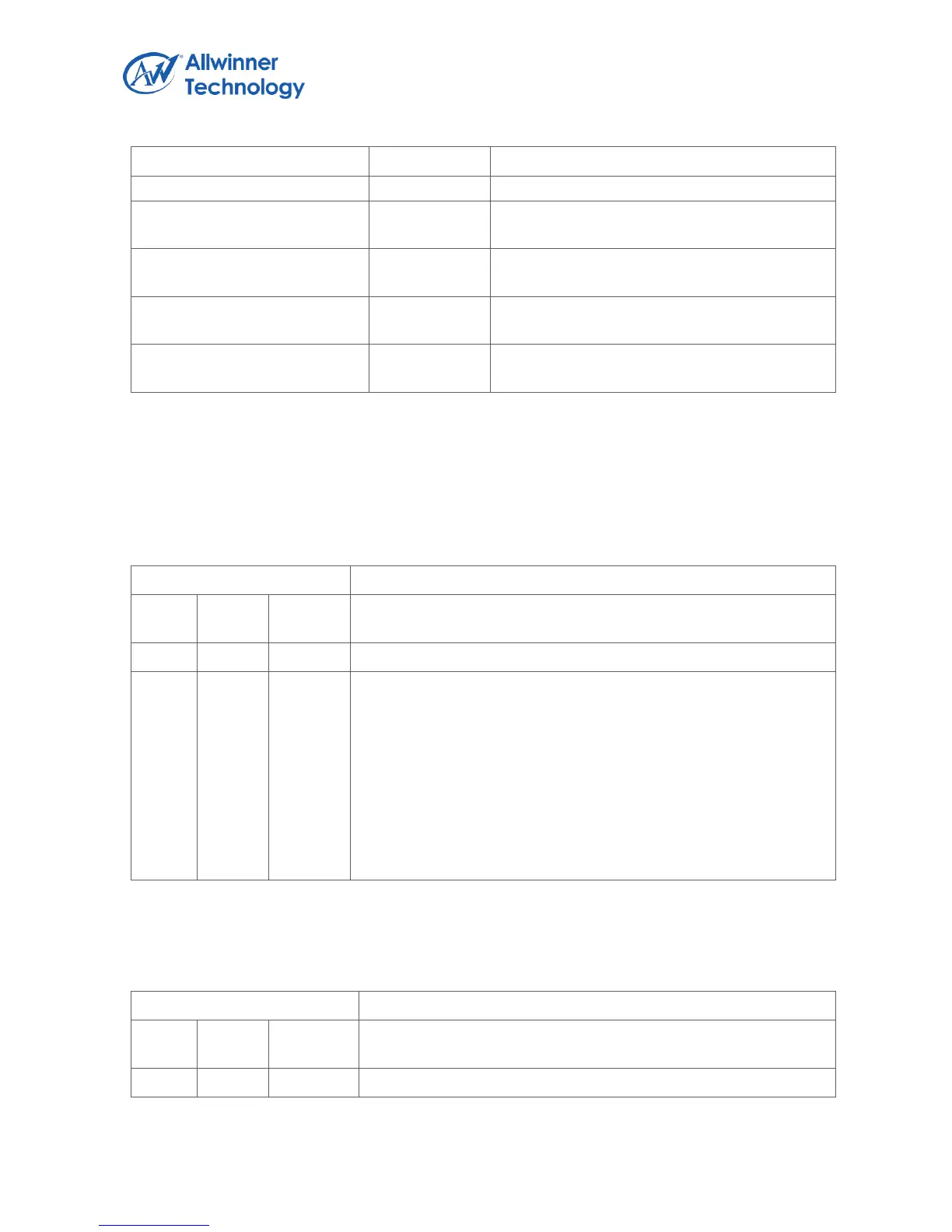
5.3.4. DEFE Register Description
5.3.4.1. DEFE_EN_REG
Register Name: DEFE_EN_REG
EN
DEFE enable
0: Disable
1: Enable
When DEFE enable bit is disabled, the clock of DEFE module will
be disabled
If this bit is transition from 0 to 1, the frame process control
register and the interrupt enable register will be initialed to default
value, and the state machine of the module is reset
5.3.4.2. DEFE_FRM_CTRL_REG
Register Name: DEFE_FRM_CTRL_REG