A20 User Manual (Revision 1.2) Copyright © 2013 Allwinner Technology Co., Ltd. All Rights Reserved. Page 570 / 812
Offset:
Pipe0:0x5000-0x53FF
Pipe1:0x5400-0x57FF
Pipe palette color table SRAM block
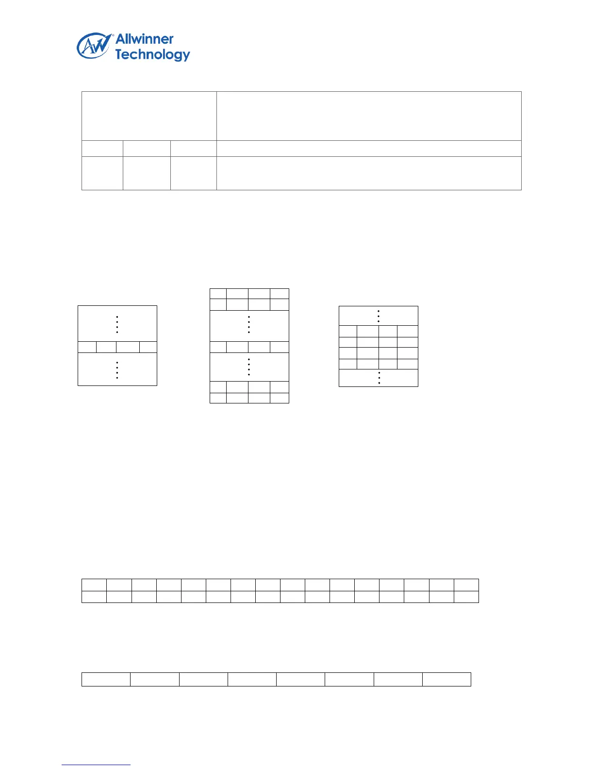
In this mode, RAM array is used for palette lookup table, each pixel in the layer frame buffer is treated
as an index into the RAM array to select the actual color.
The following figure shows the RAM array used for palette lookup and the corresponding colors
output.
n Rn Gn Bn
On chip SRAM array
5 38 133 28
Inputting external
frame buffer data
(8bpp)
Output color
28 R28 G28 B28
On chip SRAM for palette lookup
5.4.4.53. INTERNAL FRAME BUFFER MODE
In internal frame buffer mode, the RAM array is used as an on-chip frame buffer, each pixel in the
RAM array is used to select one of the palette 32-bit colors.
1bpp:
Bit
31 30 29 28 27 26 25 24 23 22 21 20 19 18 17 16
15 14 13 12 11 10 09 08 07 06 05 04 03 02 01 00
2bpp:
Bit
31 30 29 28 27 26 25 24 23 22 21 20 19 18 17 16