A20 User Manual (Revision 1.2) Copyright © 2013 Allwinner Technology Co., Ltd. All Rights Reserved. Page 804 / 812
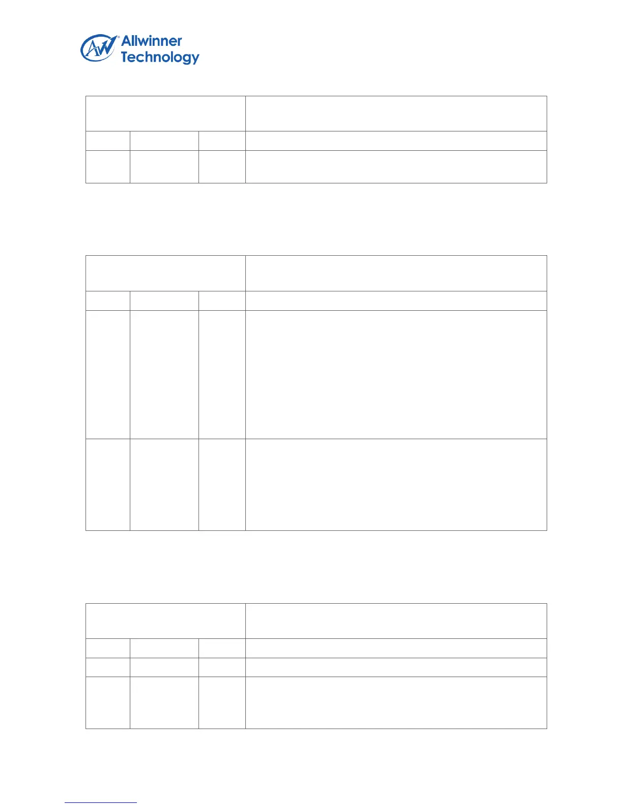
Register Name: KP_CTL
Default Value: 0x0000_0000
6.17.3.2. KEYPAD TIMING REGISTER
Register Name: KP_TIMING
Default Value: 0x0200_0100
DBC_CYCLE
Keypad Debounce Clock Cycle n
It is used for filter switching noises. When row input is low
level, the Keypad Interface would delay (n+1) clock to check
whether it is still keeping on low level. If it is true, the Keypad
Interface would scan the external keypad’s state and get these
state into internal registers. After scan, the interrupt is
generated if enabled.
Notes: The value below 0x10 can’t be used.
SCAN_CYCLE
Keypad Scan Period Clock Cycle n
When the Keypad Interface is enabled, it would scan the
external keypad in period. The period time is 8*(n+1)/kp_clk.
The kp_clk is input clock for Keypad Interface from CCU.
Notes: The value below 0x10 can’t be used.
6.17.3.3. KEYPAD INTERRUPT CONFIGURE REGISTER
Register Name: KP_INT_CFG
Default Value: 0x0000_0000
REDGE_INT_EN
Keypad input rising edge (key release) interrupt enable
0: Disable