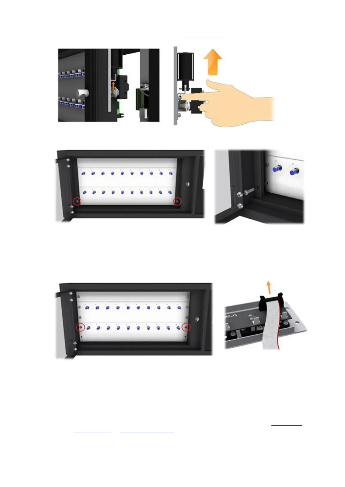
5. Reach inside and open the door manually by moving the door lock catch up.
6. Using a 4mm Allen Key, remove the Cover Panel screws one at a time and remove the cover panels.
7. Using a large flat bladed screwdriver, carefully remove the blanking strip at the top and remove the two
receptor strips and carefully disconnect the receptor ribbon cable. Put the receptor strips in a safe place until
needed, noting where they came from as they must be returned to the same location.
NOTE: It is essential that the receptor strips are replaced in the same location from which they
were removed otherwise the system will not function correctly.
8. Disconnect the following cables from the Control PCB taking note of how and where they connect.
Door Lock Cable
Power Cable
Receptor Cable
NOTE: For more details on the various PCB connections, please refer to the 8bit Control
PCB Diagrams or 16bit I/O PCB layout section of the Traka32 Help Guide.