EN
NOTE
Scrupulously comply with local regulations for the disposal of packaging.
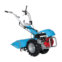
6.1 FITTING TILLER WITH CUTTER BAR
WARNING
Always fit accessories with the engine off and power take-off control lever (R, Fig. 3)
in position “N” (power take-off disengaged). During assembly, always pay attention
to the working tools of the accessories.
NOTE
For assembling accessories, see chapter 14 OPTIONAL ACCESSORIES.
6.1.1 Fitting the Quickfit
Remove the power take-off protective cover (A, Fig. 4). Grease the mating parts. Fit the coupling
(B, Fig. 5) to the machine power take-off and position the Quickfit (C, Fig. 5), securing with the
two nuts (F, Fig. 5).
6.1.2 Cutter bar assembly
Raise the accessory lock lever (D) of the Quickfit (Fig. 6). Grease the mating parts. Insert the
cutter bar body engagement (E, Fig. 6) as far as it will go. Lower the lever (D, Fig. 7) to lock the
cutter bar.
NOTE
If the accessory lock lever (D, Fig. 7) does not fully lower after it has been inserted, move
the accessory to allow the lever pin to engage in the cutter bar body engagement hole.
6.1.3 Fitting the wheels
Fit the wheels on the tiller hubs using the 4 bolts (G, Fig. 8).
WARNING
Make sure the arrow made by the tire tread pattern faces the direction of travel (A,
Fig. 8).
6.1.4 Fitting the brake control cables
Attach the pin (P, Fig. 9) to the brake control lever (T, Fig. 9) of the hub, and secure the sheath
(S, Fig. 10) in the clip.
WARNING
Check that the right hand brake lever on the handlebar controls the braking action
on the right wheel, and the left hand brake lever on the handlebar controls the
braking action on the left wheel. If not, invert the brake cables.
68