FI002K0018v1530hUK – THS/21 Instruction manual for installation, use and maintenance
5
MAINTENANCE
ORIGINAL INSTRUCTION 181
5.4 Extraordinary maintenance procedures
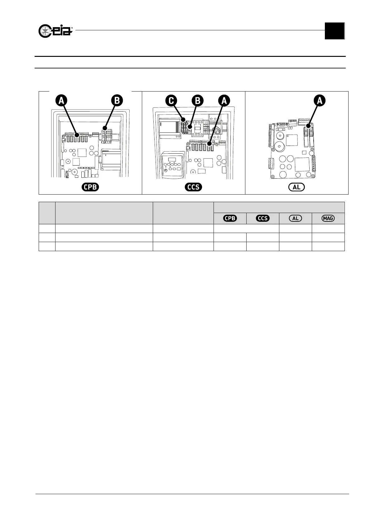
5.4.1 Changing fuses
The figure shows the position and rating of the fuses fitted to the device. Refers to electrical diagrams
too.
Ref. Description Fuse type
Electrical diagram reference
A
Relays contacts protection
5x20 T 2,5A/250V
F1, F2, F3, F4, F5, F6 F1, F2 -
B
Protection on ALM 24V input
5x20 T 2,5A/250V
F10 F10 - -
C
AC/DC input protection
5x20 F 10A/250V
- F11, F12 - F20, F21