3
FI002K0018v1530hUK – THS/21 Instruction manual for installation, use and maintenance
INSTALLAZIONE
114 ORIGINAL INSTRUCTION
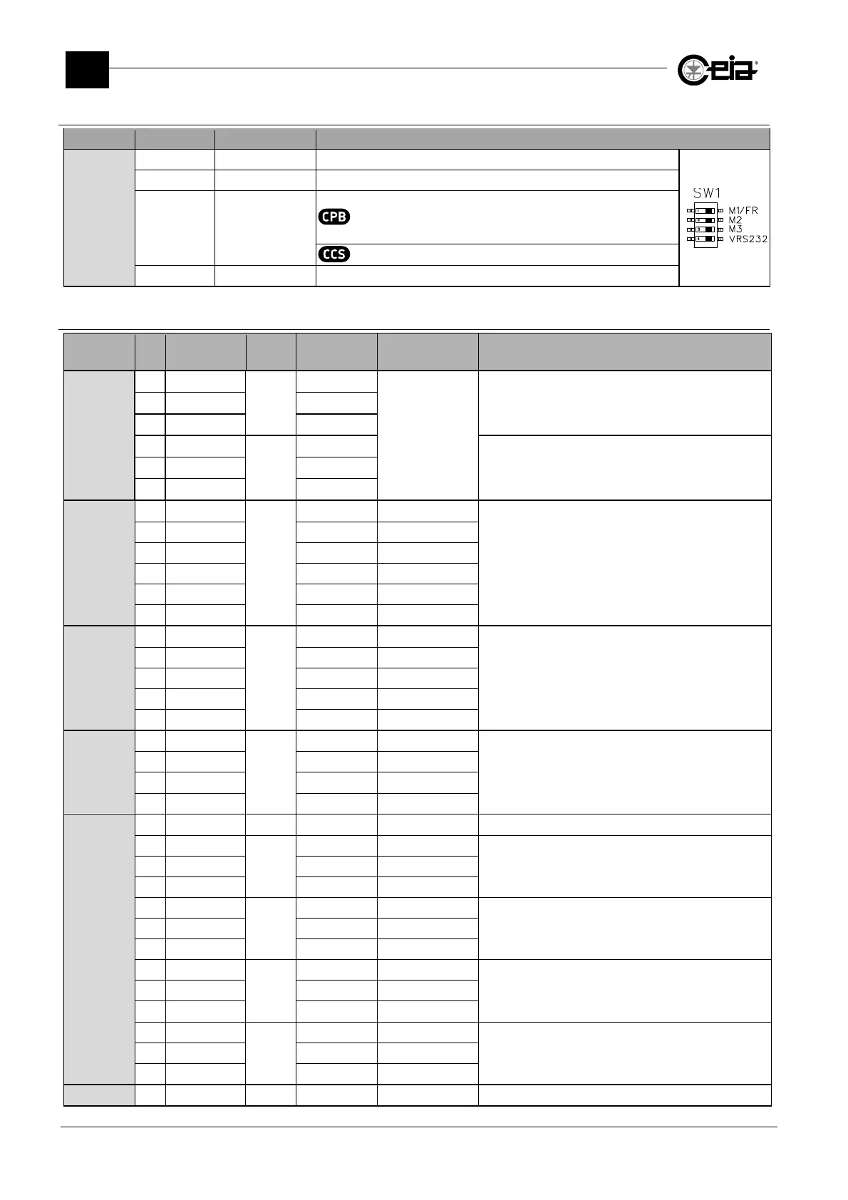
3.7.2 Settings of SW1 minidip
Connector Label Default value Description
SW1
M1/FR OFF Reserved
M2 OFF Reserved
M3 OFF
OFF: ejection activated (through EJECT NO/EJECT NC) in
case of Metal Detector power off.
ON: ejection NOT activated in case of power off.
The minidip ha no effect.
M4 OFF +24V enabled on pin1 J10
3.7.3 00211AL_ card
Connector Pin Label IN/OUT Type
Range/Max.
value
Function
J1
1 C
Output
common
30 V AC/DC 2.5A
Ready relay
2 NC N.C. contact
3 NO N.O. contact
4 C
Output
common
Ejector relay
5 NC N.C. contact
6 NO N.O. contact
J2
1 GND
Reserved
GND
Reserved for RCU connection
2 GND GND
3 TXD Data
4 RXD Data
5 +5V +5 V
6 +V +24 V
J3
1
-
+24 V 100 mA max
RS-232 serial connection
The 24 V on pin 1 is present only if the minidip VRS232
of switcher SW1 is set to ON. By default it is set to
OFF.
2 RXD
3 TXD
5 0 V
6 DTR
J4
1 GND
-
GND
Auxiliary serial port communication
2 TXD Data
3 RXD Data
4 +V +24 V 150 mA max
J5
1 GND
2 +Vin
Input
24V
Connection of ejection confirmation sensor
3 EJ.CONFIRM
4 0V 0V
5 +Vin
1
Input
24V
Connection of the synchronization photocell
6 Photocell
7 0V 0V
8 +Vin
1
Input
24V
Connection of a reset push-button
9 Reset
10 0V 0V
11 +Vin
1
Input
24V
Connection of an encoder
12 ENCODER
13 0V 0V
J6 Reserved