FI002K0018v1530hUK – THS/21 Instruction manual for installation, use and maintenance
3
INSTALLAZIONE
ORIGINAL INSTRUCTION 113
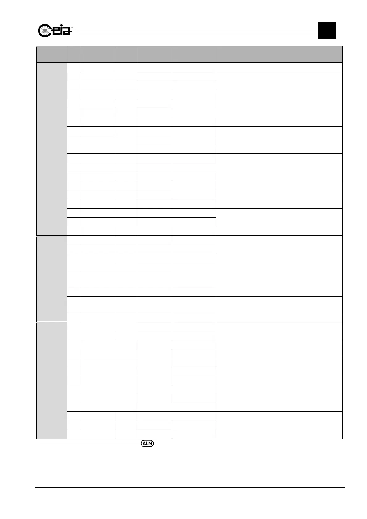
Connector Pin Label IN/OUT Type
Range/Max.
value
Function
J17
1 GND
2 0V 0V
Connection of bin full level sensor
3 BIN FULL Input
4 +Vin 24V
2
5 0V 0V
Connection of an encoder
Maximum pulse frequency: 3 kHz
Type: push-pull 24 V
6 Encoder Input
7 +Vin 24V
2
8 0V 0V
Connection of a low pressure sensor
9 Low pressure
Input
10 +Vin 24V
2
11 0V 0V
Connection of a reset pushbutton (NO)
12 Reset Input
13 +Vin 24V
2
14 0V 0V
Connection of the synchronization photocell
15 Photocell Input
16 +Vin 24V
2
17 0V 0V
Connection of ejection confirmation sensor
18 EJ.CONFIRM Input
19 +Vin 24V
2
J18
1
1 GND GND
Connection of the beacon and horn
2 0V 0 V
3 RED LAMP Output Fault signal 0/24V
4 YELLOW L. Output Alarm signal 0/24V
5 BLUE LAMP Output
Test req.
signal
0/24V
6 HORN Output Sound signal 0/24V
7 SPARE LAMP Output
Reset
backlight
0/24V
Backlighting of external button connected to the
RESET input, activated by the Reset request
8 WHITE L. Output Main signal 24V
J19
1
1 GND GND
2 0V 0 V
3 EXT EM BUTTON
EXT EM
BUTTON
External emergency button (NC single contact)
If not used, keep jumpered
4 EXT EM BUTTON
5 EM STOP 1A
EM STOP 1
External emergency button connections (NC double
contact) 1 of 2. If not used, keep jumpered
6 EM STOP 1B
7
K1 NC -
Reserved for connection to relay K1.
With Control Power Box, keep jumpered.
8
9 EM STOP 2A
EM STOP 2
External emergency button connections (NC double
contact) 2 of 2. If not used, keep jumpered
10 EM STOP 2B
11 -
Reserved for the connection with the contactor K1
12 -
13 -
1
Connector present only on card, full version
2
The +Vin power supply can provide an overall maximum current of 150mA.