3
FI002K0018v1530hUK – THS/21 Instruction manual for installation, use and maintenance
INSTALLAZIONE
112 ORIGINAL INSTRUCTION
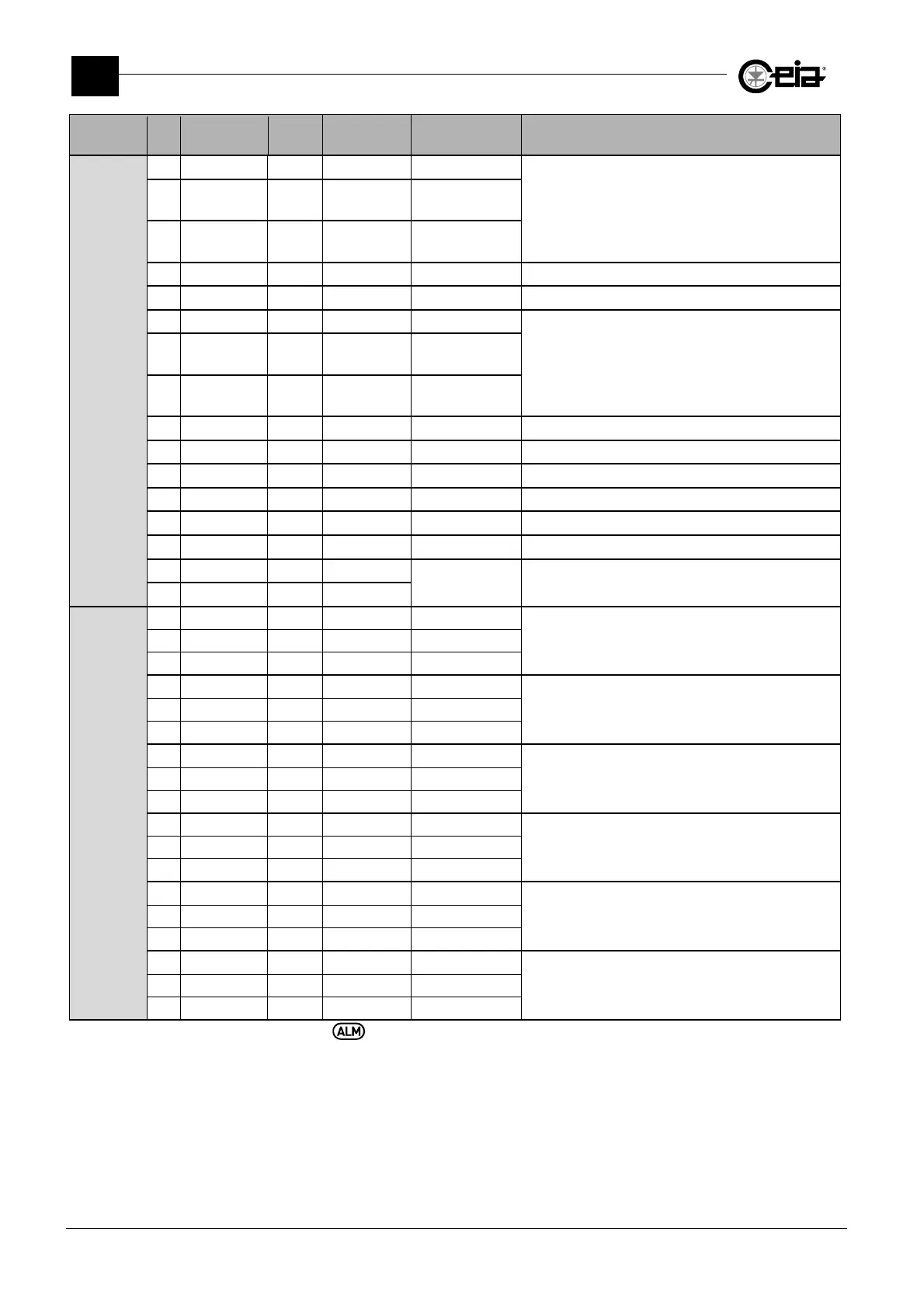
Connector Pin Label IN/OUT Type
Range/Max.
value
Function
J15
1 0V 0V
Reserved
2
Right align.
photocell
Input
3
Right align.
valve
Output 0-24V
4 0V 0V
5
6 0V 0V
Reserved
7
Left align.
photocell
Input
8
Left align.
valve
Output 0-24V
9 0V 0V
10
11 0V 0V
12
13
14
15 0V 0V
Connection of Bin electric lock
16 Bin unlock Output 24V
2
J16
1
1 0V 0V
Connection of ejection system check sensor
2 Ej. check Input
3 +Vin 24V
2
4 0V 0V
Connection of ejector position check sensor
5 EJ.POS. CHK Input
6 +Vin 24V
2
7 0V 0V
Connection of a button (NA) to activate Test
request
8 IN AUX1 Input
9 +Vin 24V
2
10 0V 0V
Connection of bin absent sensor
11 Bin absent Input
12 +Vin 24V
2
13 0V 0V
Connection of Metal Detector inhibition signal or to
force the ejection cycle
14 Inhibition Input
15 +Vin 24V
2
16 0V 0V
Connection for Following Conveyor enabling signal
by means of a clean contact
17 Foll.Conv. Input
18 +Vin 24V
2
1
Connector present only on card, full version
2
The output can provide an overall maximum current of 150 mA. In case of an emergency, the output is set to 0 V.