Air conditioning system
Installation
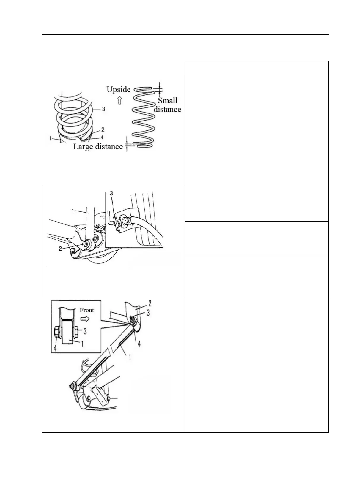
1 - Rear axle; 2-Spring seat; 3-Coil spring; 4-Step
portion
1. Install the coil spring with its closed
end facing upward and open end facing
downward, and ensure that its end is firmly
installed on the spring seat.
△!
Caution
As shown in the figure, make the spring
end close to the step portion of the lower
seat.
1 - Shock absorber; 2-Lower mounting bolt;
3-E-ring
2. Install the rear shock absorber lower
mounting bolts.
3. Remove the jack from the rear axle.
4. Install the E-ring of the brake flexible
hose.
1 -
Lateral thrust rod; 2-Vehicle body; 3-Bolt; 4-Nut
5. Install the lateral thrust rod onto the
vehicle body, and refer to the figure for the
correct installation direction of the bolts.
△! Caution
Do not tighten the nut.