Exterior trims
3.2.5 Power door lock actuator
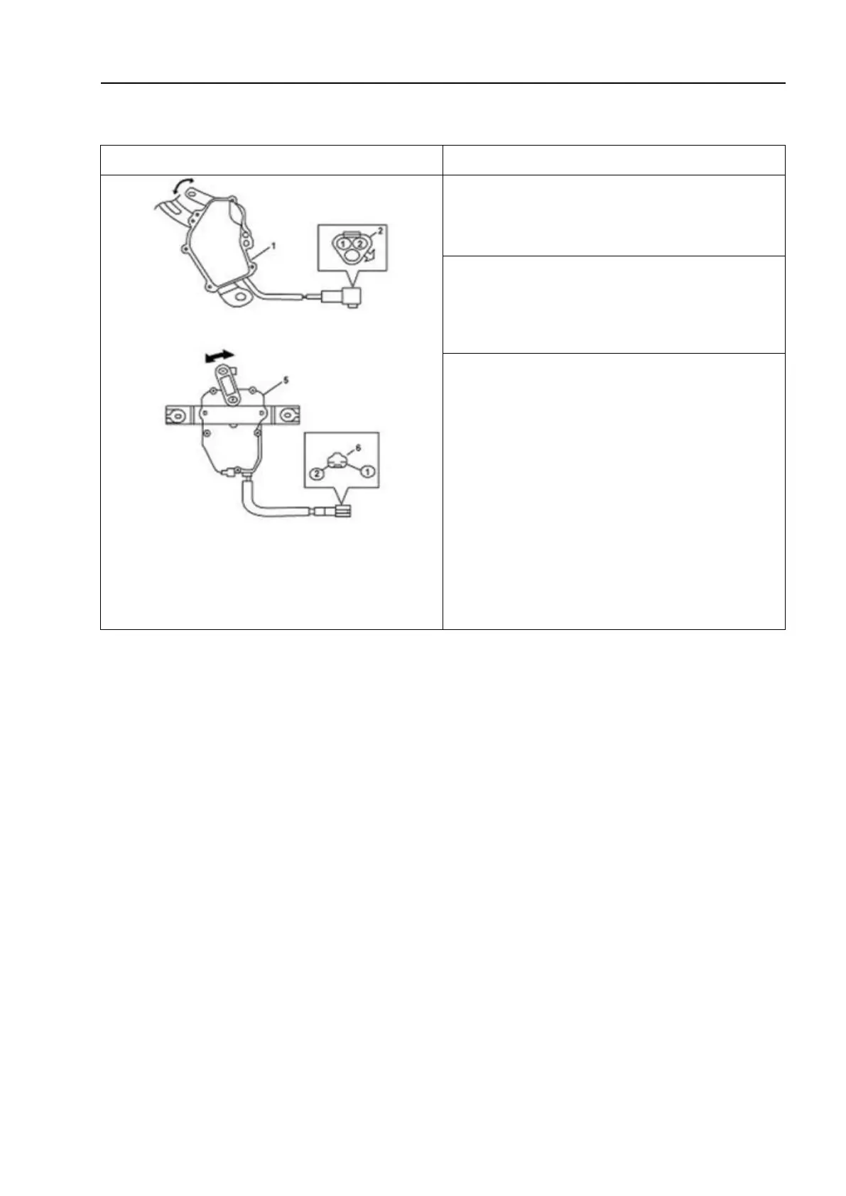
1-Front door lock actuator; 2 - Front door lock
actuator regulator;5-Rear door lock actuator;
6 -Rear door lock actuator regulator.
1. Disconnect the harness connector of
the power door lock actuator.
2. Connect the (+) and (-) terminals of the
low voltage battery to the terminals "1" and
"2".
3. If the (-) pole is connected to the wiring
post “1”, it results in “locking”; while
connecting it to the wiring post “2” results
in “releasing”. This certifies that the
actuator is functioning normally.