Steering system
Internal
storage
read/write
fault
Internal storage area
data read/write error
VMCU
vehicle
speed
signal
invalid
Vehicle speed is
invalid for a duration
of t>10 * cycle time
At least one
MCU_VEH_SPD is valid
within the cycle of the
message, 1 event
CAN
network
fault,
MCU_VEH_S
PD has no
feedback
Check the CAN
network and
MCU_VEH_SPD
Information
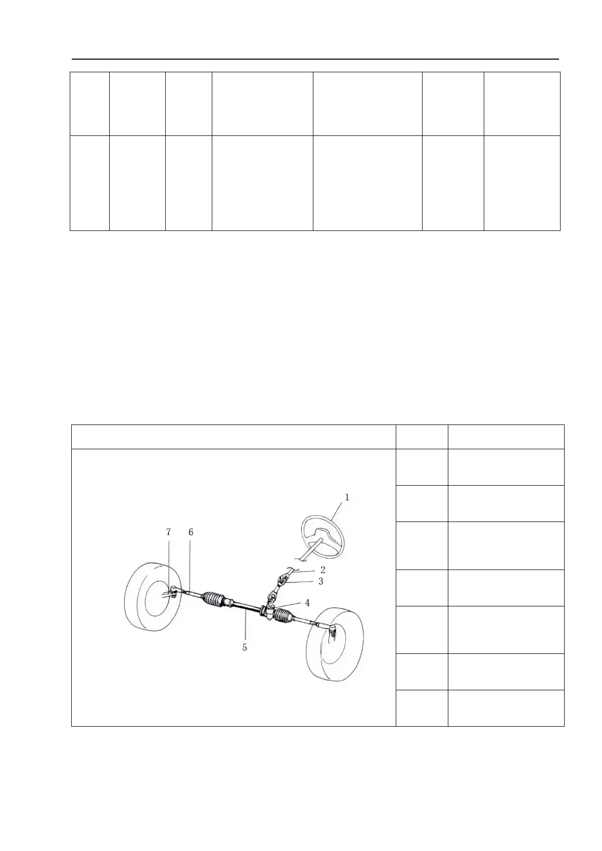
10.2 Steering connecting rod
10.2.1 Overview
The rack and pinion steering system consists of two main elements, one is the rack and
the other is the pinion. When the steering wheel is turned, this rotational motion is
transmitted through the steering shaft, the steering shaft universal joint, and then to the
pinion. As the pinion and rack mesh with each other, this action continues to be transmitted
to the rack, thereby changing the linear motion of the vehicle. This is how the steering force
is transmitted to the steering knuckle of the steering wheel through the steering tie rod.
Steering shaft
universal joint
 Loading...