2. Install the door lock ring.
• Move the lock ring up and down so that
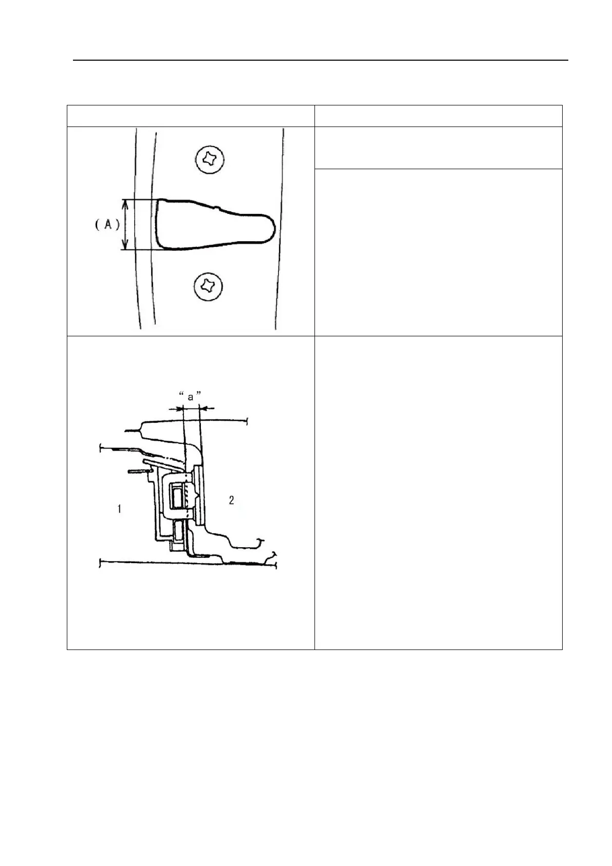
its axis is approximately in a straight line
with the center (A) of the lock groove.
△! Caution
The lock ring should be placed
horizontally and moved vertically,
without adjusting the door lock.
3. Adjust the gasket so that the door
remains in contact with the vehicle body
when closed.
• In order for the door lock ring to be
correctly positioned in the front and rear
directions, adjustments can be made by
increasing or decreasing the number of
adjusting gaskets inserted between the
vehicle body and the lock ring. Dimension
"a" should be adjusted to the specified
value.
Dimension "a": 12.6-14.6mm(0.50-0.57in.)
△!
Caution
Regularly inject lubricating grease into
the joint of the lock ring.