EasyManua.ls Logo

Cessna 182 1978 - Page 431

Cessna 182 1978
680 pages
Print Icon
To Next Page IconTo Next Page
To Previous Page IconTo Previous Page
Loading...
MODEL
182
&
T182
SERIES
SERVICE
MANUAL
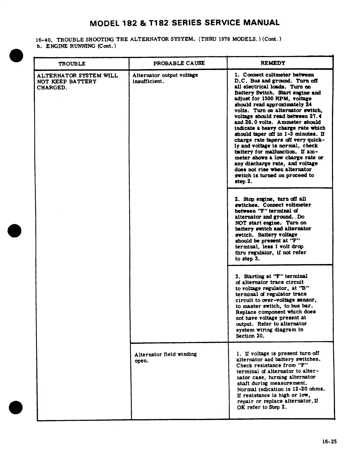
16-40,
TROUBLE
SHOOTING
THE
ALTERNATOR
SYSYEM.
(THRU
1978
MODELS.
)
(Cont.)
b.
ENGINE
RUNNING
(Cont.)
TROUBLE
PROBABLE
CAUSE
REMEDY
ALTERNATOR
SYSTEM
WILL
Alternator
output
voltage
1.
Connect
coltmeter
between
NOT
KEEP
BATTERY
insufficient.
D.C.
Bus
and
ground.
Turn
off
CHARGED.
all
electrical
loads.
Turn
on
Battery
Switch.
Start
engine
and
adjust
for
1500
RPM,
voltage
should
read
approximately
24
volts.
Turn
on
alternator
switch,
voltage
should
read
between
27.4
and
28.0
volts.
Ammeter
should
indicate
a
heavy
charge
rate
which
should
taper
off
in
1-3
minutes.
If
charge
rate
tapers
off
very
quick-
ly
and
voltage
is
normal,
check
battery
for
malfunction.
If
am-
meter
shows
a
low
charge
rate
or
any
discharge
rate,
and
voltage
does
not
rise
when
alternator
switch
is
turned
on
proceed
to
step
2.
2.
Stop
engine,
turn
off
all
switches.
Connect
voltmeter
between
"F"
terminal
of
alternator
and
ground..
Do
NOT
start
engine.
Turn
on
battery
switch
and
alternator
switch.
Battery
voltage
should
be
present
at
"F"
terminal,
less
1
volt
drop
thru regulator,
if
not
refer
to
step
3.
3.
Starting
at
"F"
terminal
of
alternator
trace
circuit
to
voltage
regulator,
at
"B"
terminal
of
regulator
trace
circuit
to
over-voltage
sensor,
to
master
switch,
to
bus
bar.
Replace
component
which
does
not
have
voltage
present
at
output.
Refer
to
alternator
system
wiring
diagram
in
Section
20.
Alternator
field
winding
1.
If
voltage
is
present
turn
off
open.
alternator
and
battery
switches.
Check
resistance
from
"F"
terminal
of
alternator
to
alter-
nator
case,
turning
alternator
shaft
during
measurement.
Normal
indication
is
12-20
ohms.
If
resistance
is
high
or
low,
repair
or
replace
alternator,
If
OK
refer
to
Step
2.
16-25

Table of Contents