Programmable DC Power Supply (with Solar Array Simulation) 62000H Series
Operating & Programming Manual
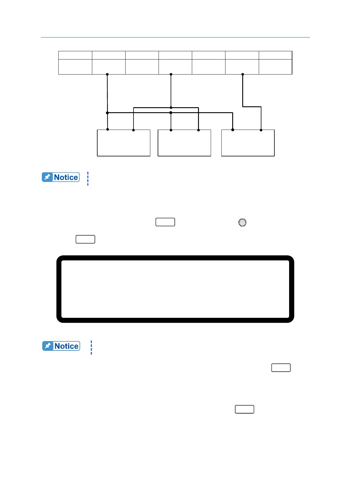
Figure 3-125
Key in at least 5 digits for each calibration point to ensure the Power
Supply accuracy after calibration.
3.3.7.4.3 Calibration Procedure (Example: Model 62150H-600S)
1. In the CALIBRATION page, press “ ” or turn the “Rotary” ( ) knob to set CHOICE
= 4.
2. Press “ ” to display the current calibration options as shown in Figure 3-126.
[ A P G V O L T A G E C A L I B R A T I O N ]
C H E C K A P G C O N N E C T I O N A N D P R E S S
[
E N T E R ] _
( S E T
) I N P U T V O L T A G E F O R S E T T I N G
=
0 . 5 V
A C T U A L
A P G I N P U T V O L T A G E = 0 . 0 0 0 _
V
(
S E T
) I N P U T V O L T A G E F O R S E T T I N G
= 8 .
0
V
A C T U A L
A P G I N P U T V O L T A G E = 0 . 0 0 0 _
V
Figure 3-126
1. If an HP 34401 is used, DVM1 and DVM2 can be connected to the
front and rear measurement input terminals respectively.
3. Insure the interface connection on the rear panel is correct and then press “ ” to
confirm.
4. Input a 0.5V voltage signal on Pin 4. The cursor stops at position [1] as shown in Figure
3-127. Adjust the Power Supply to 0.5V±0.2V and use DVM1 to measure the reading of
the Power Supply. Input the voltage read by DVM1 and press “ ” to confirm.
+
+
−
−
DC Power
Supply
DVM
1
DVM
2
−
+
1
+
12
VAPI API GND AVO
_SETV
14
...
4 ...
6
AVO
_
MEAS