Manual Operation
Figure 3-127
5. Press “
” and input an 8.0V voltage signal on Pin 4. The cursor stops at position [2]
as shown in Figure 3-127. Adjust the Power Supply to 8V±0.2V and use DVM1 to
measure the reading of the Power Supply. Input the voltage read by DVM1 and press
“ ” to confirm.
6. Press “ ” again and the system will set the output voltage of Pin 6 on the rear
panel to 0.5V and the cursor will stop at position [3] as shown in Figure 3-128. Input the
voltage read by DVM2 and press “ ” to confirm.
Figure 3-128
7. Press “
” again and the system will set the output voltage of Pin 6 on the rear
panel to 8.0V and the cursor stops at position [4] as shown in Figure 3-128. Input the
voltage read by DVM2 and press “ ” to confirm.
8. The APG Voltage calibration is done once the above actions are completed. To save
the calibration data, pressing “ ” will display a confirmation page as shown in Figure
3-129. Press “ ” or turn the “Rotary” (
) to set SAVE=YES and press “ ” to
save it. If there is no need to save it, press “
” to return to the Calibration screen.
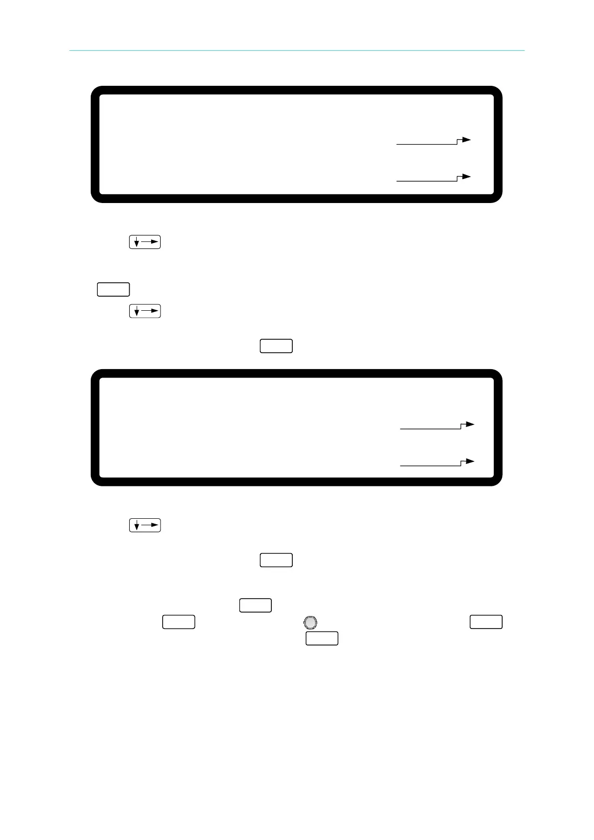
[ A P G V O L T A G E C A L I B R A T I O N
]
C H E C K A P G C O N N E C T I O N A N D P R E S S [ E N T E R ]
( S E T ) I N P U T V O L T A G E F O R S E T T I N G = 0 . 5 V
A C T U A L
A P G I N P U T V O L T A G E = 0 . 0 0 0 _ V
( S E T ) I N P U T V O L T A G E F O R S E T T I N G = 8 . 0 V
A C T U A L A P G I N P U T V O L T A G E = 0 . 0 0 0 V
[
1
]
[ 2 ]
[ A P G V O L T A G E C A L I B R A T I O N ]
( M E A . ) O U T P U T V O L T A G E F O R M E A S U R E = 0
. 5 V
A C T U A L A P G O U T P U T V O L T A G E =
0 . 0 0 0
_ V
( M E A . ) O U T P U T V O L T A G E F O R M E A S U R E =
8 . 0 V
A C T U A L A P G O U T P U T V O L T A G E = 0 . 0 0 0 V
[
3 ]
[ 4 ]