Use the keys and to select the different options.
To conrm the selection, press the key
.
If no key is pressed for 5 minutes, the display screen changes automatically to the default
screen.
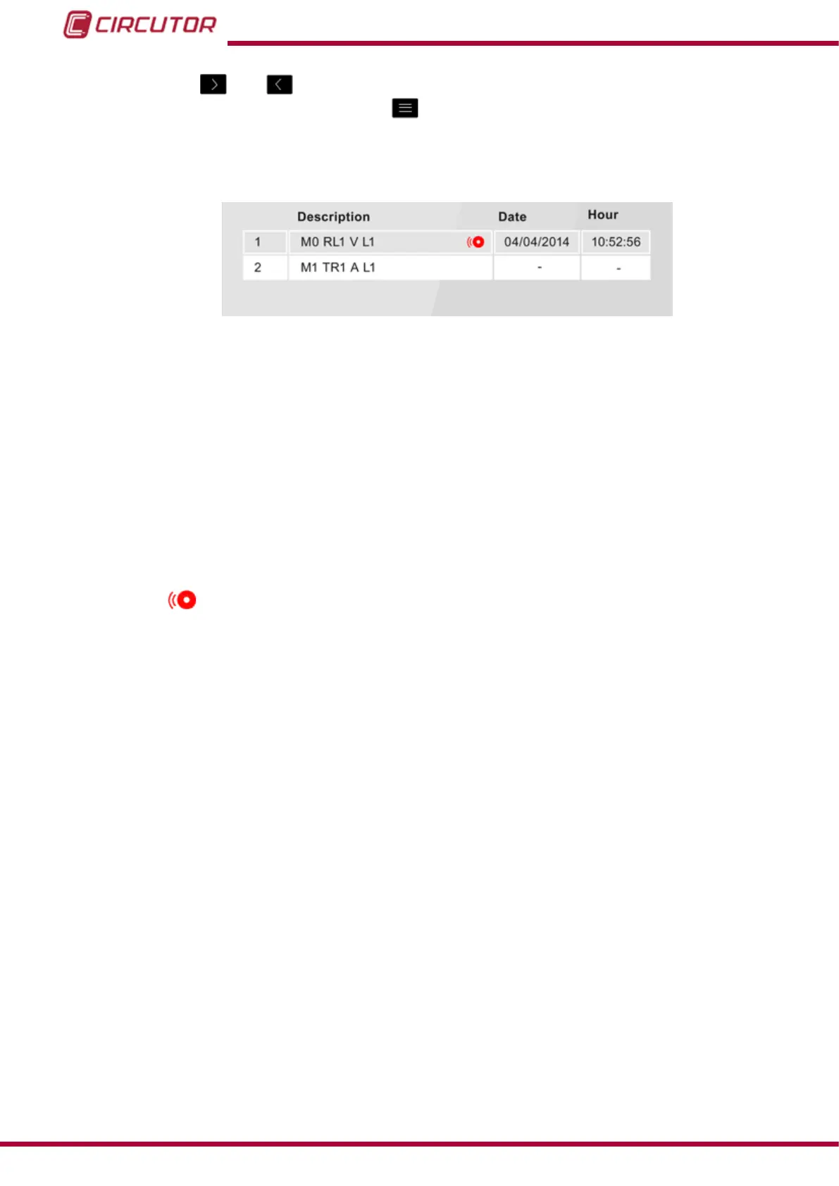
Figure 90: Alarm menu description table.
The programmed alarms description table, Figure 90, is made up of 4 columns:
Cd. : Indicates the code of the variable that controls the programmed alarm, Table 21.
Description : Description of alarm that you have programmed.
Example: M0 RL1 V L1
M0, Indicates that an alarm is integrated in the unit.
RL1, Indicates that it is output 1 of the relay digital outputs.
V L1, The variable that controls the alarm is Phase-Neutral Voltage of phase 1.
The icon indicates that the alarm has been activated.
Date : If the alarm has been activated, the date when this occurred will be displayed.
Time : If the alarm has been activated, the time when this occurred will be displayed.
106
CVM-B100 - CVM-B150
Instruction Manual