Example:
Query: Reading the position of input channels.
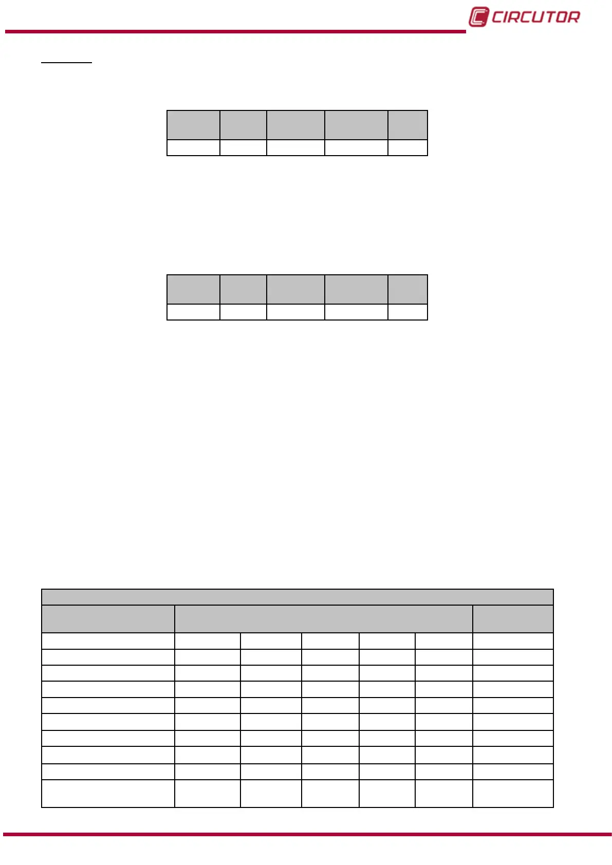
Address
Func-
tion
Initial reg-
ister
No. of regis-
ters
CRC
0A 04 2850 0001 XXXX
Address: 0A, Peripheral number: 10 in decimal.
Function: 04, Read function.
Initial Register: 2850, register address.
No. of registers: 0001, number of registers to be read.
CRC: XXXX, CRC character.
Response:
Address
Func-
tion
No. of
Bytes
Register CRC
0A 04 02 0924 XXXX
Address: 0A, Responding peripheral number: 10 in decimal.
Function: 04, Read function.
No. of bytes: 02, No. of bytes received.
Register: 0924 (0000100100100100bin) Indicates:
- (0000100100100100bin) The direction of the currents does not change,
- (0000100100100100bin) Current channel 3 is assigned to L3,
- (0000100100100100bin) Current channel 2 is assigned to L2,
- (0000100100100100bin) Current channel 1 is assigned to L1,
- (0000100100100100bin) Voltage channel 3 is assigned to L3,
- (0000100100100100bin) Voltage channel 2 is assigned to L2,
- (0000100100100100bin) Voltage channel 1 is assigned to L1,
CRC: XXXX, CRC character.
6.3.7.18.- Conguration of custom screens
These parameters occupy 1 register each.
Table 52: Modbus memory map: Conguration variables (Conguration of the parameter customisation screens)
Conguration of the parameter customisation screens
Configuration variable Address
Valid data
margin
1 parameter screens Screen 1 Screen 2 Screen 3 Screen 4 Screen 5
Variable 2968 2978 2988 2998 29A8 Table 55
Not used 2969 2979 2989 2999 29A9 0
Not used 296A 297A 298A 299A 29AA 0
Not used 296B 297B 298B 299B 29AB 0
Phase 296C 297C 298C 299C 29AC Table 56
Not used 296D 297D 298D 299D 29AD 0
Not used 296E 297E 298E 299E 29AE 0
Not used 296F 297F 298F 299F 29AF 0
Consumption or
Generation
(1)
2970 2980 2990 29A0 29B0
0: Consumption
1: Generation
197
Instruction Manual
CVM-B100 - CVM-B150