A.- Protective cove version 1
To install, rstly remove the protective cover of the expansion connector located at the rear of
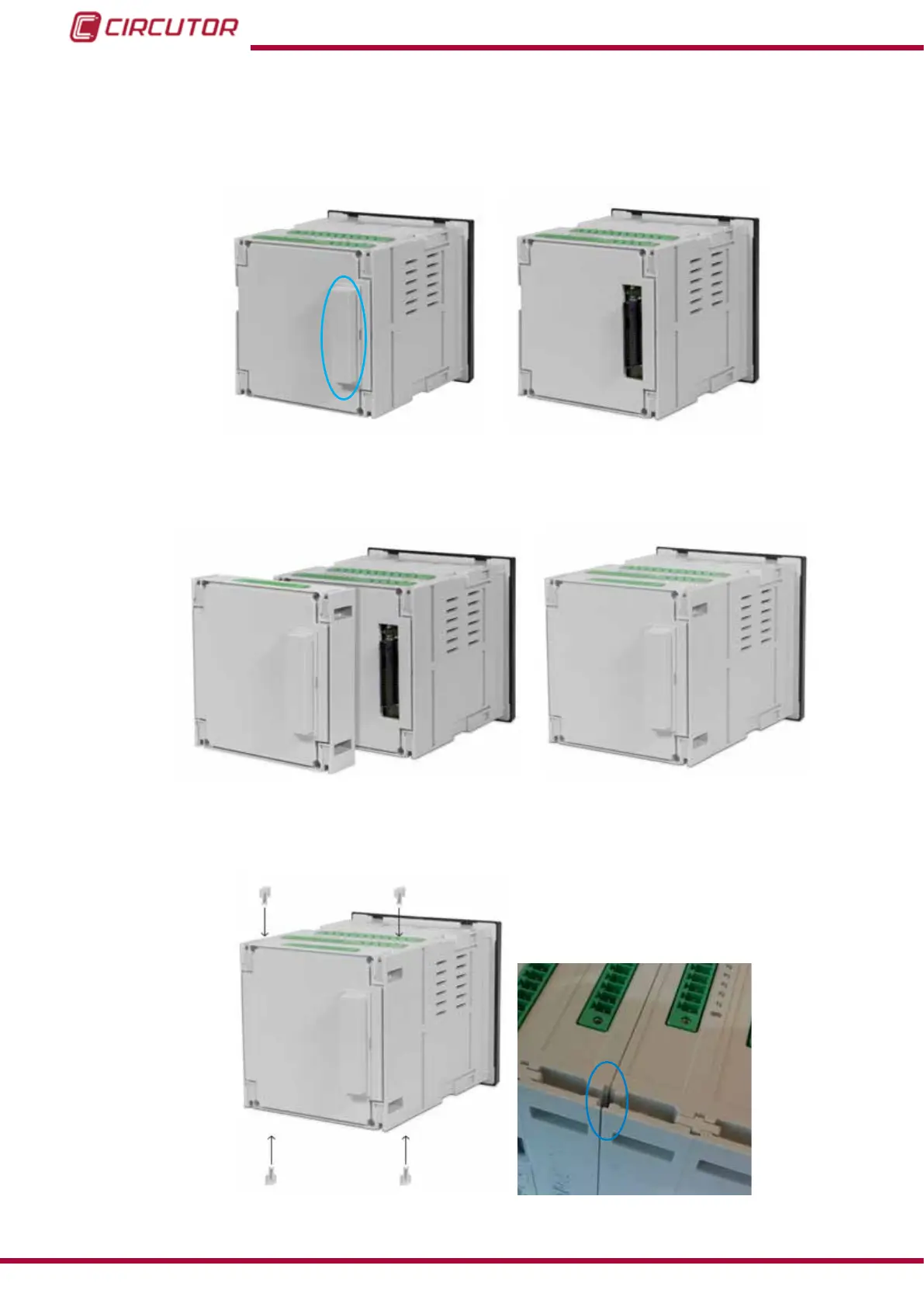
the unit, Figure 143.
Figure 143: Remove the expansion connector cap.
connect the expansion module to the unit, Figure 144,
Figure 144: Connect the expansion module.
and secure it by inserting the 4 fastening pins into the corresponding slots, Figure 145.
Figure 145: Insert the fastening pins into the corresponding slots.
210
CVM-B100 - CVM-B150
Instruction Manual