1-87
Catalyst 3750-X and 3560-X Switch Software Configuration Guide
OL-25303-03
Chapter 1 Configuring IP Unicast Routing
Configuring Multi-VRF CE
Multi-VRF CE Configuration Example
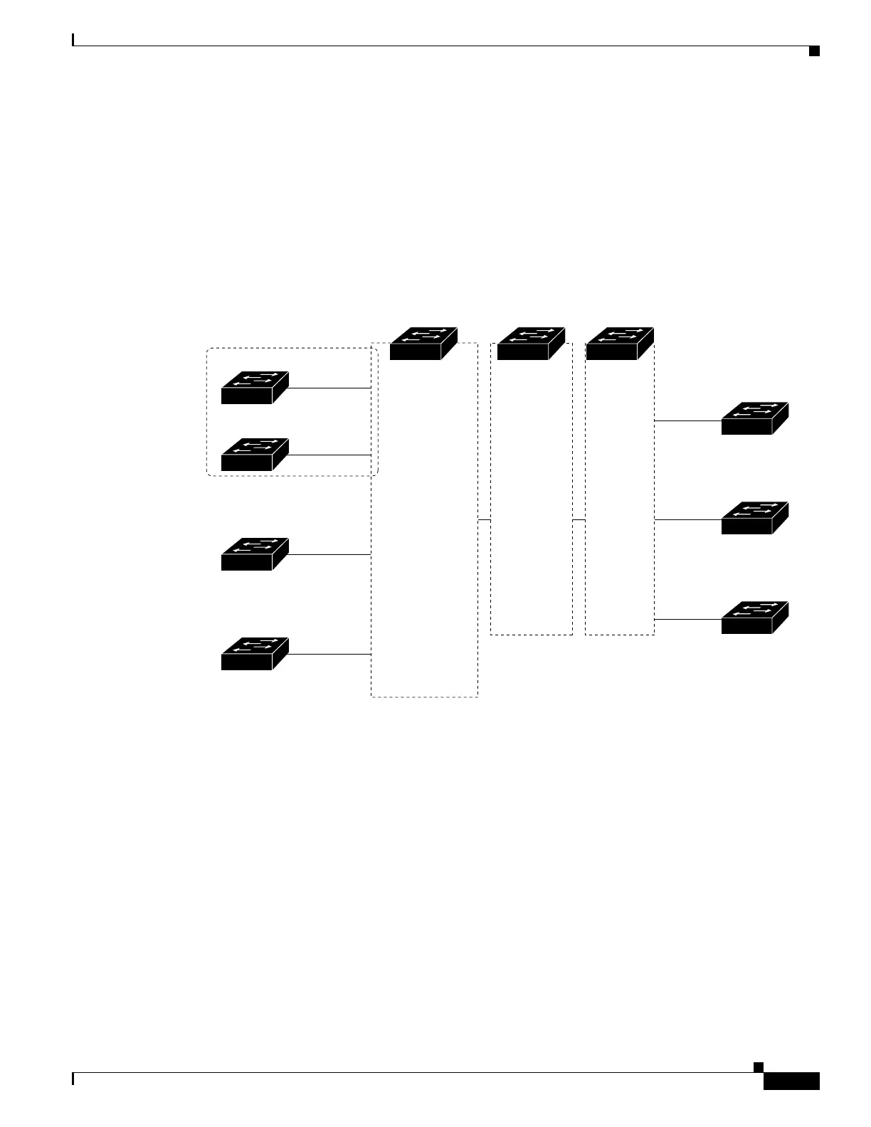
Figure 1-7 is a simplified example of the physical connections in a network similar to that in Figure 1-6.
OSPF is the protocol used in VPN1, VPN2, and the global network. BGP is used in the CE to PE
connections. The examples following the illustration show how to configure a switch as CE Switch A,
and the VRF configuration for customer switches D and F. Commands for configuring CE Switch C and
the other customer switches are not included but would be similar. The example also includes commands
for configuring traffic to Switch A for a Catalyst 6000 or Catalyst 6500 switch acting as a PE router.
Figure 1-7 Multi-VRF CE Configuration Example
Configuring Switch A
On Switch A, enable routing and configure VRF.
Switch# configure terminal
Enter configuration commands, one per line. End with CNTL/Z.
Switch(config)# ip routing
Switch(config)# ip vrf v11
Switch(config-vrf)# rd 800:1
Switch(config-vrf)# route-target export 800:1
Switch(config-vrf)# route-target import 800:1
Switch(config-vrf)# exit
Switch(config)# ip vrf v12
Switch(config-vrf)# rd 800:2
Switch(config-vrf)# route-target export 800:2
Switch(config-vrf)# route-target import 800:2
Switch(config-vrf)# exit
Configure the loopback and physical interfaces on Switch A. Gigabit Ethernet port 1 is a trunk
connection to the PE. Gigabit Ethernet ports 8 and 11 connect to VPNs:
Switch A
Switch D
VPN1
VPN2
CE1
Global network
208.0.0.0
Fast
Ethernet
8
Gigabit
Ethernet
1
101386
PE CE2
Switch E
108.0.0.0
Fast
Ethernet
7
Switch F
118.0.0.0
Fast
Ethernet
11
Switch G
168.0.0.0
Fast
Ethernet
3
VPN1
VPN2
Global network
Switch H
Switch J
Switch K
CE = Customer-edge device
PE = Provider-edge device
Switch B Switch C
 Loading...


