1-12
Catalyst 3750-X and 3560-X Switch Software Configuration Guide
OL-25303-03
Chapter 1 Clustering Switches
Planning a Switch Cluster
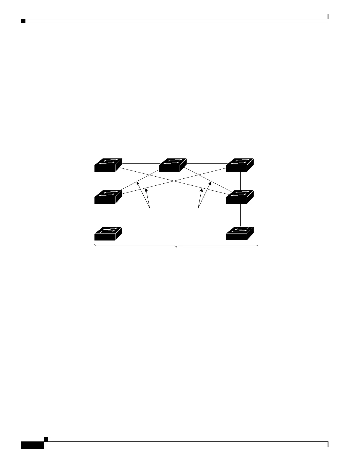
• Each standby-group member (Figure 1-7) must be connected to the cluster command switch through
the same VLAN. In this example, the cluster command switch and standby cluster command
switches are Catalyst 3560-E, Catalyst 3750-E, Catalyst 3560-X, or Catalyst 3750-X cluster
command switches. Each standby-group member must also be redundantly connected to each other
through at least one VLAN in common with the switch cluster.
Catalyst 1900, Catalyst 2820, Catalyst 2900 XL, Catalyst 2950, and Catalyst 3500 XL cluster
member switches must be connected to the cluster standby group through their management
VLANs. For more information about VLANs in switch clusters, see these sections:
–
“Discovery Through Different VLANs” section on page 1-7
–
“Discovery Through Different Management VLANs” section on page 1-7
Figure 1-7 VLAN Connectivity between Standby-Group Members and Cluster Members
Automatic Recovery of Cluster Configuration
The active cluster command switch continually forwards cluster-configuration information (but not
device-configuration information) to the standby cluster command switch. This ensures that the standby
cluster command switch can take over the cluster immediately after the active cluster command switch
fails.
Automatic discovery has these limitations:
• This limitation applies only to clusters that have Catalyst 2950, Catalyst 2960, Catalyst 2970,
Catalyst 3550, Catalyst 3560, Catalyst 3560-E, Catalyst 3560-X, Catalyst 3750, Catalyst 3750-E,
and Catalyst 3750-X command and standby cluster command switches: If the active cluster
command switch and standby cluster command switch become disabled at the same time, the passive
cluster command switch with the highest priority becomes the active cluster command switch.
However, because it was a passive standby cluster command switch, the previous cluster command
switch did not forward cluster-configuration information to it. The active cluster command switch
only forwards cluster-configuration information to the standby cluster command switch. You must
therefore rebuild the cluster.
101326
Management
VLAN 16
Standby
command device
VLAN 16
VLAN 9
VLAN 9
Command
device
Passive
command device
Member devices
Management
VLAN 9
VLANs 9,16 VLANs 9,16
Management
VLAN 16