1-27
Catalyst 3750-X and 3560-X Switch Software Configuration Guide
OL-25303-03
Chapter 1 Configuring Interface Characteristics
Using the Ethernet Management Port
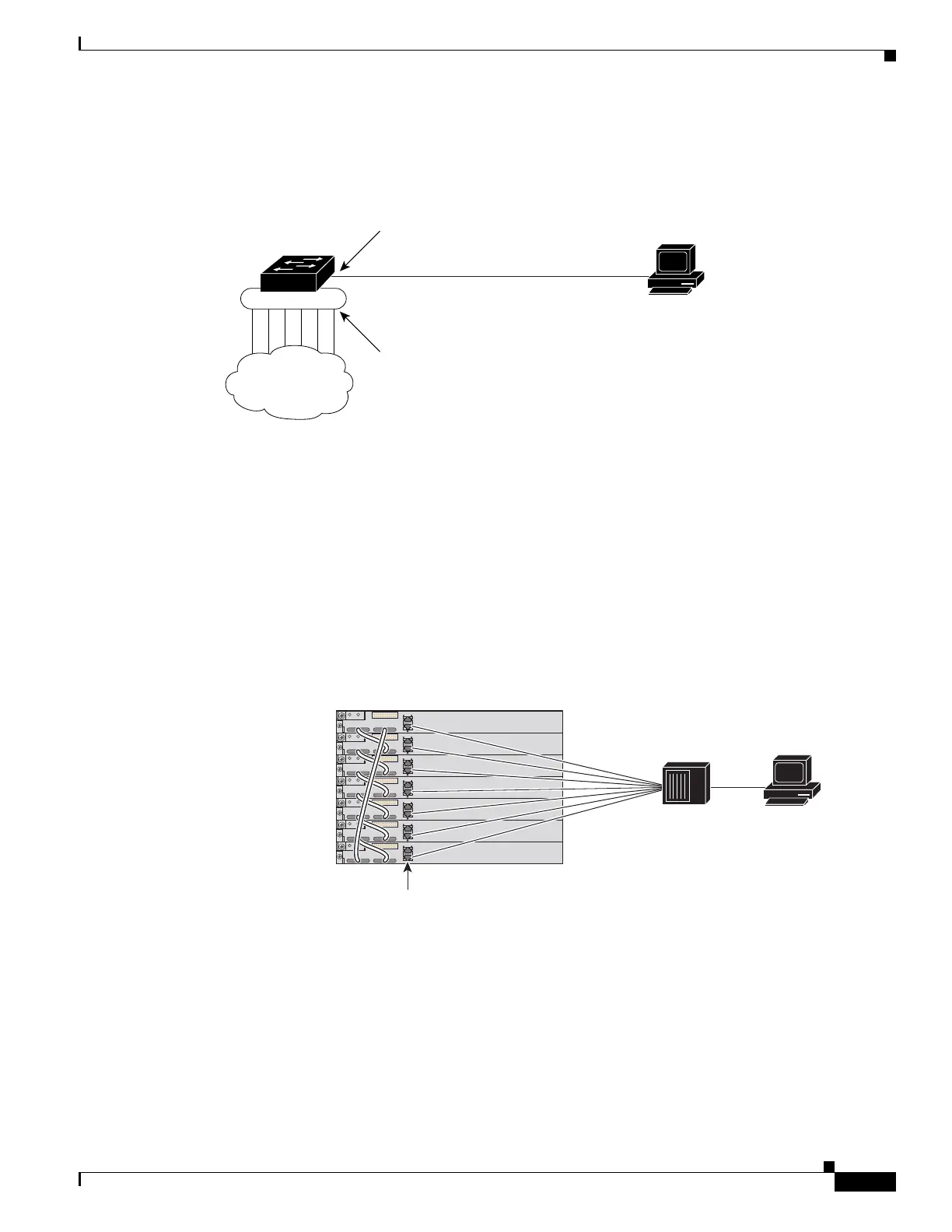
For a Catalyst 3560-X switch or a standalone Catalyst 3750-X switch, connect the Ethernet management
port to the PC as shown in Figure 1-2.
Figure 1-2 Connecting a Switch to a PC
In a stack with only Catalyst 3750-X or Catalyst 3750-E switches, all the Ethernet management ports on
the stack members are connected to a hub to which the PC is connected. The active link is from the
Ethernet management port on the active switch through the hub to the PC. If the active switch fails and
a new active switch is elected, the active link is now from the Ethernet management port on the new
active switch to the PC. See Figure 1-3.
In a mixed switch stack with Catalyst 3750 switches, only the Catalyst 3750-E and Catalyst 3750- X
stack members are connected to the PC through the Ethernet management ports. The active link is from
the active switch, a Catalyst 3750-E or Catalyst 3750- X switch to the PC. If the active switch fails and
the elected active switch is not a Catalyst 3750-E or Catalyst 3750- X switch (switch 2), the active link
can be from a stack member to the PC.
Figure 1-3 Connecting a Switch Stack to a PC
By default, the Ethernet management port is enabled. The switch cannot route packets from the Ethernet
management port to a network port, and the reverse.
Even though the Ethernet management port does not support routing, you might need to enable routing
protocols on the port (see Figure 1-4). For example, in Figure 1-4, you must enable routing protocols on
the Ethernet management port when the PC is multiple hops away from the switch and the packets must
pass through multiple Layer 3 devices to reach the PC.
157549
Switch
PC
Network
cloud
Ethernet
management
port
Network
ports
Ethernet management ports
Switch stack
Stack member 1
Stack member 2
Stack member 3
Stack member 4
Stack member 5
Stack member 6
Stack member 7
157550
PC
Hub
Catalyst 3750 switches do not have Ethernet management ports.
Catalyst 3750 switches in a mixed stack are not connected to the hub.