1-2
Catalyst 3750-X and 3560-X Switch Software Configuration Guide
OL-25303-03
Chapter 1 Configuring IEEE 802.1Q and Layer 2 Protocol Tunneling
Understanding IEEE 802.1Q Tunneling
tagged packets. A port configured to support IEEE 802.1Q tunneling is called a tunnel port. When you
configure tunneling, you assign a tunnel port to a VLAN ID that is dedicated to tunneling. Each customer
requires a separate service-provider VLAN ID, but that VLAN ID supports all of the customer’s VLANs.
Customer traffic tagged in the normal way with appropriate VLAN IDs comes from an IEEE 802.1Q
trunk port on the customer device and into a tunnel port on the service-provider edge switch. The link
between the customer device and the edge switch is asymmetric because one end is configured as an
IEEE 802.1Q trunk port, and the other end is configured as a tunnel port. You assign the tunnel port
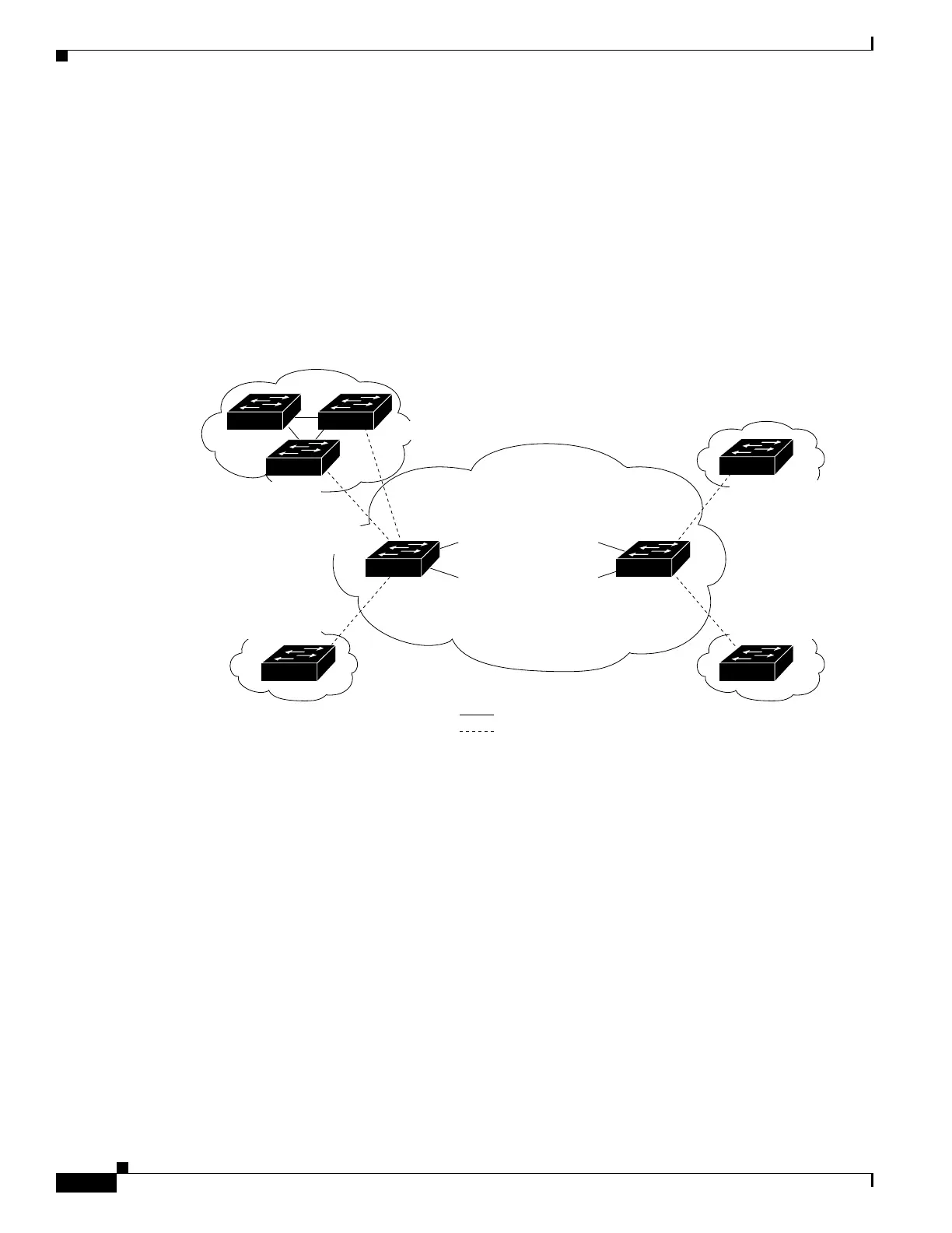
interface to an access VLAN ID that is unique to each customer. See Figure 1-1.
Figure 1-1 IEEE 802.1Q Tunnel Ports in a Service-Provider Network
Packets coming from the customer trunk port into the tunnel port on the service-provider edge switch
are normally IEEE 802.1Q-tagged with the appropriate VLAN ID. The the tagged packets remain intact
inside the switch and when they exit the trunk port into the service-provider network, they are
encapsulated with another layer of an IEEE 802.1Q tag (called the metro tag) that contains the VLAN
ID that is unique to the customer. The original customer IEEE 802.1Q tag is preserved in the
encapsulated packet. Therefore, packets entering the service-provider network are double-tagged, with
the outer (metro) tag containing the customer’s access VLAN ID, and the inner VLAN ID being that of
the incoming traffic.
When the double-tagged packet enters another trunk port in a service-provider core switch, the outer tag
is stripped as the switch processes the packet. When the packet exits another trunk port on the same core
switch, the same metro tag is again added to the packet. Figure 1-2 shows the tag structures of the
double-tagged packets.
Customer A
VLANs 1 to 100
Customer B
VLANs 1 to 200
Customer B
VLANs 1 to 200
Customer A
VLANs 1 to 100
Tunnel port
VLAN 40
Tunnel port
VLAN 30
Trunk
ports
Trunk
ports
Tunnel port
VLAN 30
Tunnel port
VLAN 40
Service
provider
802.1Q trunk port
802.1Q trunk port
802.1Q trunk port
802.1Q trunk port
802.1Q trunk port
74016
Trunk
Asymmetric link
Tunnel port
VLAN 30
802.1Q trunk port
802.1Q trunk port
802.1Q trunk port
802.1Q trunk port